

faizanbrohi
-
Posts
203 -
Joined
-
Last visited
Never
Content Type
Profiles
Forums
Events
Posts posted by faizanbrohi
-
-
hello again , after a long time i am back , and this time i have found two new crystal controlled IC's that suffice my needs , MC2833 FM Transmitter and MC13136/35 and MC3362 FM Reciever IC's . These IC's are crystal controlled and i think they will be fine for my Radio controlled Car. But Will it Work good for DTMF . It think it might. Although motorola does not manufacture these IC's , but these IC's Are available here in Pakistan at a very Cheap Price of Less than a Dollar . The Main Pain in the Butt is finding the crystals and the Inductors Just right and since the Transmitter is low power i have to build a Power Amplifier of 1W/0.5W for it. The Schematics and pinouts are attached.


-
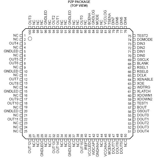
okay 33 pins are NC which are not connected so this leaves only 67 , out of which 16 are output to led which leaves 51 pins out of which 16 are for DIN and DOUT which leaves 35 pins and out of which only 2 pins are for register select for brightness control and DCLK , the only question i want to ask is that the maximum rating of DCLK is 15Mhz and there is no min or typical value given , so since 15Mhz is maximum so i can drive it with a 1Mhz clock refrence using Timer TLC552 . That is the only question please helppp....
-
please can anyone help me on this subject
-
you might have varactors in the opposite direction as in my circuit.
-
no i think it is somewhat your pulse rate . ;D , like a ecg machine
-
I am Planning to build a parallel port led dimmer using ti's TLC5904 which uses 8 data inputs for adjusting the brightness or in other words current . you can control upto 15 LED's using this IC .
I know how to interface the parallel port But there is some complication in this is , i don't understand what is a DOUT For , DIN DCLK are used for input for brighness control , and there input will come from a parallel port , since a parallel port is a 8 bit ouput from a computer . i don't know why dclk is for , do i have give external clock pulse . here is the ic pinout
-
But if you can implement AFC on the reciever side , why not in the transmitter side . But i think for my project that radio is sufficient ,
-
yeah i get it , this means the TX-500 will be rock solid transmitter if it is PLL Controlled . and one more thing the IC i have for the radio is a KA22425 and also it's equivalent CXA1618M , well the PDf is attached . i know it is not PLL Controlled but why it is stable . i also used it to check my walkie talkie and what do you know , it is quite stable also , it was also quite stable with my FM transmitters , i previously build . it also has a LED indicator to indicate if the channel is selected
-
Hello again , i have a question how can i implement a crystal oscillator i found on the net in my modulator and replace the LC circuit . the desciption and circuits of fundamental crystal oscillators and overtone crystals are given here http://hem.passagen.se/communication/txo.html
One more thing how can i use it as a refrence oscillator -
Well The PCb Layouts for the power meter are made , now its time to prepare the board and practically test it . will update soon


-
Still i must say that Toner Transfer method is the best , i have printed an adaptor which is 7 to 10 mil and with perfect results . Just using simple glossy paper , which just cost's nothing compared to the photographic method and an iron. i have also tried the Photoresist method but with not sufficient results. i still Stick with The Toner Transfer method .
i will show some pics of the board in the next post. -
Well here is the schematic of the Power meter . i am feeling a little sleepy , will make assemble and develop the board for the oscillator and power meter , until then
astalavista baby !!!
-
WHy not use a step up boost voltage regulator , like the ti's UC2577 , but it has a bulky circuit and high amperage . i think a small step up boost voltage regulator with 0.5 A and 12 V regulation voltage would be ok .
But then again why bother , and just connect the 12 Volt battery pack directly ;D -
So if i remove it , it will be ok for DTMF and if i remove it . it will work for voice.
now i will post the power meter shortly. one more thing i am putting a 12V voltage regulator for both the VHF power meter and as well as the VHF Amplifer. is it ok. -
Hello i am back with some modifications . here is a v1.1 of the oscillator TX-500 . i have added a 1nF capacitor for better stability . the rest is that varactor diodes have changed their posistion. Now i will build the power meter... Asap


-
But in the original schematic it is with this configration , take a look here .. i am a little confused here ???
and look at the power meter also ...
really confused , don't know what to do , then just to experiment. ???
I think the varactor are in the right direction because it is actuallly reverse biased and the voltage from the variable resistor varies at the cathode.

-
well i have completed the Oscillator section and here are the PCb board layouts and schematics .
For your question that i will have crowded bands , the answer is that 105mhz FM Band has no radio station , so it will work for me . and keep in mind this is only a educational project. SO NO LICENCING REQUIRED ;)
Now i am making the power meter to test the circuit .


-
I will be using a 12V battery pack. and also be using MPSH10 VHF/UHF Transistor , and what do you know , it has really low frequency drift. i will also be making a board layout with ground plane. so well this all will reduce frequency drift , but using a PLL would be really nice to reduce frequency drifts. but PLL Controllers are not so easy to make.
-
Housing it in a mettalic case will reduce the frequency drifts. and the supply voltage is also regulated with a 7805 regulator. but the thing that will have affect is only temprature.
-
i have a FM Radio kit which i have tested and it is built around a samsung am/fm radio IC , it is a full superhet FM Reciever with preamphasis and PLL Tuning , It uses a Gang Capacitor for tuning , i would require a frequency filter of some sort for the dtmf frequecies. so when there is no signal the car should not be doing anything. The wire is insulated actually , the color of insulation and the qualtiy of the picture makes it look like bare wire.
The question is how can i apply a quartz crystal here , my fm radio reciever has a ceramic resonater for stability. but how can i apply it in the transmitter section.
hmm but i can also use a varactor diode for stability in the oscillator section , the tunable coil L1 gives good stability also.
Here is a link for the DTMF Remote control. http://wiredworld.tripod.com/tronics/remote_control.html -
pics continued....


-
Well First things first here are the pictures of the coils i made (L1 is a tunable coil with ferrite core for tuning) , and you require a lower value of emitter resistors like 100 ohm for the RF Transistors . To shield it you require a metallic shield between the driver and the amplifier. The pcb's will be made shortly and will post them soon.


-
hello Paul_J,
well as chinmoy1955 said LM324 is not suitable for audio because of it's high noise and THD , but LM324 is often used as a comparator for analog circuits. you can find mixer and audio circuits which use texas instruments tL074 or 72 or 71 here http://sound.westhost.com/ -
Today i will go to get ferrite beads and the RF Transistors. Well The emitter resistors i don't know which values to put , do they have to be greater in term of power i mean 1/2w or 1w or 2w maybe or in value and Wattage.
Well i am going to build a prototype and i am going to build three different units first , the Oscillator seperate , the Seperatar/Amplifier seperate , but how do i shield it ???
one more thing i will make the power meter also seperate.
i have another idea of building an oscillator , why not use a opamp with gain bandwidth product of almost 500Mhz , and then use a summer with gain 2 and add or mix the two frequencies . it is more robust i think.


RC-(remote controlled) Car
in Electronic Projects Design/Ideas
Posted
Does anyone knows dbm to mW conversion . the output power of The Transmitter is +10 dbM , how much will be it in mWatts . ???