-
Posts
26 -
Joined
-
Last visited
Never
Content Type
Profiles
Forums
Events
Posts posted by Untitled_user
-
-
Hello! :D
After I saw this topic, I immidiately downloaded and tried this software and I have to say it's absolutely awesome. Realy impressed me.
Bravo! Thank you guys for reference! 8) -
Your transformer will provide only 3.4AAC, so the supply will provide only 2.4ADC instead of 3A.
Well, guess I gonna need satisfy with this...
If nothing else, there will be less heating problems... 8)
I will buy (or borrow, or steal ;D) theese OP AMPs, add trimmer in series with current pot and use modified parts list.
And then...
And finaly, THANK YOU!!!
It was impressive and quick as always. -
OK. Lets mess it out!
I parallel transformer secondary windings and i get 30V 4.3A AC.
And ... I buy OPA445AP's. :o
And thing is gonna work.
Will it? How?
And wich partslist to use? Need I change something more?
Cheers... ;D -
Hi.
There is no way that this circuit will work with my transformer?
Adding a parrallel R to trafo output to drop voltage? Current will be too small?
Connecting together both trafo outputs is out of question, right?
Something else?
And I really cant afford 445 OPs to me... international shipping price + $30 for 445's is too much for me ??? :'(
There's really nothing to do? Only new transformer? -
Hello! ;D
I am looking this power supply for some time and I was planning to build it; in fact I still am interessted in this project, but I need some answers, so, please:
1. I have a 30/30 V transformer 100VA total, 1.7/1.7A secondary output. Can I use
it? What for output I will get?
2. What can I use instead OPA445AP? ??? Not availabile, and as I hear, expensive.
TL081? +-18V will be enough?
3. Wich partslist to use? Modified or original one?
I saw a part of conversation about this PS, (not all 60+ sites ;D) and I am
confused. I do not need high-end tip-top extreme power supply, but I even do not
want PS crashes, overheating etc. Just a nice, good working and reliable PS.
4. I assume that 10000uF/50V as C1 is gonna be just nice.
So long... -
OK, and thanks a lot!
I will buy parts as soon as i get and assembly this circuit...
Till then...
Cheers! -
Hello,
sorry about theese opto isolators...
Here is the filtered list... -
Audioguru?
-
-
Hi,
well, i really don't know wich ones to take... never had experience with photo elements before... but, its time to change it...
I atached a list of elements from our 'local' shop... don't worry, it's only about 30 of them... ;D And I'm soory if the choice is bad... we don't have much electronic stores, and what we have is ussualy expensive... Hope it's gonna change some day...
So, please find something for me...
Have a nice day... -
Hi,
This was realy quick and professional... Very nice :D
THANKS!!!
Of course, have a question again:
Can you, please, write down some diodes and transistor pairs that can be used..?
I looked online catalog here by us and it's a bit confusing...
And, I supose that now I can directly drive analog meter form output, isn't it?
Marc -
After long time, hello again...
I'm back to bother you...
Audioguru:
I would ask you something: Would you, please, be so good to quickly sketch a schematic for me? I see that if we (better said I :-[) continue so, we would come nowhere... I belive that would not be too big problem for master like you... Please?
And if answer is yes, i would like Vcc something like 5 or 9V...
Marc -
Hi,
I was thinking a bit about that counter...
I redraw those schematics and now I'm posting them; one with LM2917, and other with 555 timer.
I do not know if this one with LM will work, but it looks damn simple ;D
And if I use the 555 circuit, I will anyway have to use freq. to voltage converter at output, am I right?
I think that would be time to pick up way to go, so, what do you sugest, and why? -
Well,
on this schematic from datasheet, I actualy wanted to ask if magnetic principe could be somehow changed with optical... i forgoted :) I belive that magnetic could not be used, beacuse it's about electric motor, so it will disturb the work of counter...
And on this design with 555 I should add a freq/voltage converter to drive a analog meter, isn't it?
So, i dont know what to do... the both solutions seems to be quite good, simple and cheap... And I ask you, masters of electronics: what to do? I'm gonnig in electronis school, we courently learning basics about analog and digital electronics u know: transistor amplifiers, multivibrators, digital logic, TTL, CMOS, voltage ragulators...so I belive that I soon wont bother you with such simple projects, and I could design some circuits at my own... ;D
And by then, I would appreciate a little help...
Marc -
Hello again...
Well, MP && Audioguru, i realy appreciate your efforts... Thank you...
So, simpliest possibile solutions seems like this one posted bellow (from datasheet ... thx audioguru), and this one at (thx MP...)
Which one do you reccomend to use and what modifications should I make to use them for my application?
Regards, Marc -
Hi,
writing just to say thank you on your posts...
I have some ideas, but curently I dont have time... Will write back tomorow...
Thanks! -
Hi,
c'mon, please help me...
I realy need help...
:( -
Hi,
don't know how to say thank you...
Well, I have never used uControlers - I know something about them, but I don't have a programer, and I don't have any idea about programing language... I'm planing to learn that because I belive they're future, but... not yet...
LM2917 is availabile.
100 x Thank you! -
Hi,
look, I'm terribly sorry about this, but I messed up... and i will completely understand
if you don't want to help me anymore... :-[
Situation is next: i was looking for ICM7226 circuit, and I found it's price in my country is almost $50... plus everything else... I must say it's way to much for me... because this counter is just a part of bigger project and I can't spend so much just on this...
I know, i'm stupid... I should look that first...
I'm realy, realy sorry about your effort, your work, your replays...
So, if you want, you can help me, if not, I understand you.
So, anybody, now I'm switching to analog meter...
Can simple 555 and an analog scale driven by freq-to-voltage converter get the +/-5% accuracy?
Or anybody has an other idea (analog/digital, doesn't mater, just to be cheaper)?
Please, help me, I realy need this circuit... -
Hi,
Thank you very, very much for helping me.
And a question about comparator - simple LM will do the job? -
Hi,
OK, I see that ICM7226 is probably the best and simplier solution.
You said that it's very easy to use... but I have never before doing something similar... I have some knowledge about digital electronic but I can't say that im master... I'm far away from that... That's the reason why I'm asking you...
So, i have downloaded a ICM7226 datasheet from Itersil web...
It contains some basic circuits with this IC. (universal counter, frequency, period counter... you know for shure...) I picked up a universal counter and tried to re - made circuit for my use... I made a schematic and I'm posting it (1024x768, would be nice wallpaper... ;D) Please, take a look and tell me what is wrong (maybe it would be easier to tell what's right... :-[) (And don't laugh to much...)
Thank you very much... -
Hi again... ;D
Well.. don't know where to begin... You surprised me a bit... :o
I have to say that ICM7226 looks very powerfull and suitable for this operation.
But, there are 2 problems:
1. I can't get one in my area... (samples maybe ;D)
2. I belive it's way to complicated for me... :-[
So, i would ask you if you can tell me some alternatives to ICM7226?
And a basic hookup? ??? Maybe?
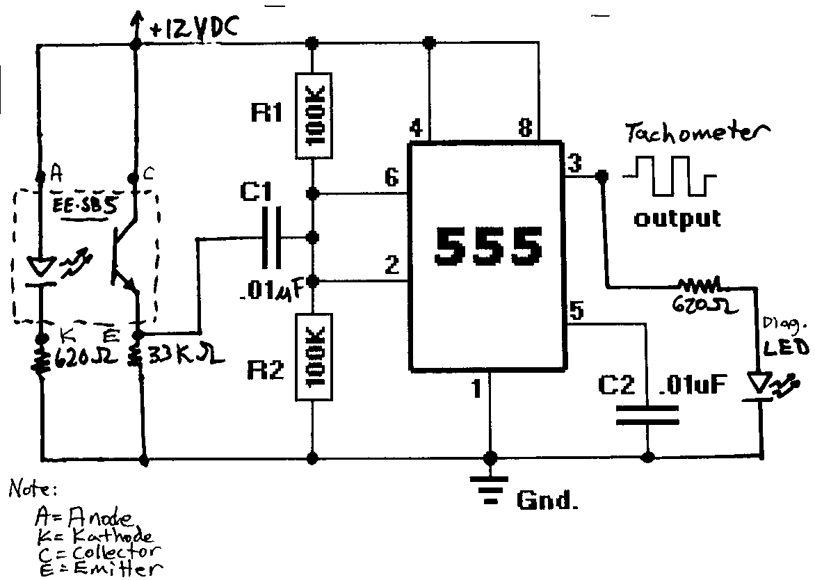
Btw. i was trying to re-made some tacho circuit that uses 555 timer. On the exit you get a square wave, and I belive that it drives some comercial tacho display...
So, I was thinking... maybe output wave could be converted with some freq - to -voltage converter to drive a analog scale... But, now I see that it can be done digital way, and even easier maybe... So, i will just forget 555 and wait for answer...
Thank you on cooperation... :) -
Hi, thanks for jumping in... :)
Well... The disk would be made from plastic, and it would be something around 15 cm wide, and more maybe.
Counting: I would like that circuit be as simple as possible - without uControlers and need for programing them. Just a sensor, counter and LED display driver. But OK, I will understand if that will not be possible.
Speed of motor is high. But, its a variable, and I actually belive that minimum will be somewhere on 1800 rpm. (120 impulses/sec)
Of course, I would like accuracy to be as high as possible, but +/- 5% won't bother me to much... -
Hi everybody...
I'm need a help about a designing one, I hope, simple electronic circuit.
So... I will try to explain what should it be... I posted an image (i know it's poor, my english isn't far away from that too... ) to understand what I mean.
So, the disk has four stripes on it, and the disk is spinning on AC motor with variable rotation speed. I need to count this stripes and show their number in one second.
I explained it this way (with stripes) because I belive it can be done with LED and phototransistor. So this looks like some kind of tachometer, just it shows number of 'stripes'/second. I was been looking on net for some tacho circuits, but i didn't find anything usefull. Yeah ... i forgot to tell: the result needed to be shown on LED display (LCD acceptable too... ;D).
I hope you know what I meaned... If someone has a idea or some circuit that can be used, please help...


Some kind of RPM counter
in Electronic Projects Design/Ideas
Posted
Hi!
I'm back again. I assembled the counter... ;)
Tooked BPW40 and ordinary white LED.
And of course, there are the problems...
1. It works just fine when I put the diode on one side of rotating disc and transistor
on the other, and cut a hole in disc so Tr can 'see' diode in one moment of
rotation. (excuse me for bad description, hard to me say it in English :'()...
But when I try to put them both on the same side and use reflection from
white/black area, it doesn't react. What can I do?
2. OK, this one I belive can be done later, but anyway: how to calibrate the
meter?
Regards