

kbyrne
-
Posts
70 -
Joined
-
Last visited
Never
Content Type
Profiles
Forums
Events
Posts posted by kbyrne
-
-
Two photos attached but they are not real clear as I discovered I need a new camera. Please view and advise as best you can. P.S. I discovered a letter in a box on the front of switch. Letter is
(A). Kevin

-
No but I have a digital camera and will upload pictures today.
-
I saw on E-Bay a lot of pots for guitars electric ect. Punch into top 100k, 10k and view them like I did while looking for 250k Alps
-
I need some help as this part has no letters, numbers ect on it. This is a NEC amplifier and it is a two position switch except the wire hook up to mother board is a flat cable type that seems to be seperated into three different cables surrounded by black plastic. Can three wires be soldered on to this cable? If no how to find a OEM part with no part number? It is a phono selector type MC/MM.
-
Thank you. No A, M in letters. Dual pot that I have found on E-Bay with 12mm shafts and 6mm shafts.
Mine is 6mm shaft size. Must be linear, will order one. Many thanks. Kevin ;D -
I have a NEC amplifier that I am working on and need to find a source of Data Sheet for ALPS potentiometers to identify the value and old part numbers. This is all there is on the pot. 305F & 250KMN. The reading
I get is 195k but that is due to fact that the shaft is busted an cannot be turned. I assume value is
250K. Where do I go for a Technical Data sheet for ALPS? -
Buy the book I have called Speaker building 101. Two companys in this country I know off specalize
in speakers. Parts Express, MCM Electronics. One of those two companys should still have book and speakers for your project. Google or Yahoo for site address and catalogs, Phone Numbers ect. -
Google for your answer or use search engine Yahoo. It is done in programs like Express SCH Capture and Express PCB then produced at home or sent to board houses. Download Eagle freeware version as it has Tutorials also.
-
Will do. I have the SCH done in Express SCH and am working on PCB now in Express PCB. I also use
Xcheck, too check DRC, & Netlists & BOM. In the future I will post results as parts are easy to find. One more problem I saw under closer examination of inconsistent SCH and PCB. Below
IC1, and above IC2 there are two 1K resistors I fail to see on the schematic. I just missed these two
facts before I posted. How all of this got buy their proof reading of that web site I do not know. Does
any one know what is the purpose of those two resistors and if they are necessary as I am new and not good at design, nodal analysis ect? -
:) Thank you I have the inductor info in my files. I like to try to build this type of project so I will give it a go and use my +15 gnd. -15 I already know all about for tone control circuits. Thank you for all responses. Best Kevin
-
Actually the address at the top of the page leads to a page that directs you to this project. Is this power supply workable with the change made to diodes Text of PCB board no matter what I use it for?
A larger amount other than 15v O 15v. What is the reason behind inductors L1 and L2 and where can I go to learn that fact? -
On the schematic D1 & D2 are at the 15v top together but on my PCB board pdf D1 & D3 are together
or am I wrong. On the schematic D3 & D4 are at the opposite 15v side of transformer but on my PDF
D2 & D4 are together. What I assumed was the text of the PCB was done wrong. On PCB PDF it goes from top to bottom D1, D2, D3 & D4. Am I right so far? ??? It should go D1, D3, D2, & D4. -
I down loaded interesting new power supply for pre amps, tone control purposes. Upon examining
the schematic and board there is a difference in diode numbers. Could some one take a look at it
and advise me if this power supply is a working design or not as I am new but know how to set up the diodes and capacitors but lack in design experience?Precision_15V_regulator_for_pre-amp_or_headphone_amplifier.pdf
-
Have you guys ever tried Pulsar Pro's version of apache lam. with magazine paper?
It is supposed to be perfect with small traces close together every time. The Lam. is
Apache AL13P sold on E-Bay and Amazon for approx. $80 to $90 dollars. -
I tried this simulator and a major error came up trying to exit. It froze my computer and would not shut down. Why? I am not experienced enough to figure it out.
-
Thanks to you I have TEX up and running fine with DOS-BOX.
-
I downloaded Pspice and it comes Zipped. How do I set it up to use? Do I need a windows emulator or DosBox? Can anybody help? Later on today I ran across a web site called faculty.physics.tamu.edu/duller/pspice/pspice71.html. On it was all the files of pspice and directions for installing the program. It is up and running, so thanks any ways. Sorry about the post it can be deleted if management wishes. The other site is necessary with your WinZip in the downloads area. If you wish I will find the correct link for all in the future. Pspice works good on windows XP 32bit.
-
Two positive power supplys hooked together the right way work out to one power supply with +/- & gnd.
The trick acording to Electronics For Dummies and or The Idiots guide to electronics is int the way the binding posts are hooked together so two Identicle 1 to 50vdc power supplys become +1 to +50vdc/-1 to -50vdc and circuit common. Make voltages as close as possible and amperage as close as possible and your circuit will just be doubled then jumpers together inside the box to three outputs. Yellow/Black/Red. I can supply the rough drawing to check out if you desire. -
What I have is a idea I need technical advise about. Needs 36vdc @ 4A. Transformer in front of this board
24vac @ 5A. A normal power supply of same transformer Bridge rectifier and 4700uf @ 50wvdc comes out the end at 36vdc. How will these parts work out as I need help figureing out which formula's to use. I need to be near as possible to 36vdc out the end for two 12-Watt amplifier boards. Are my calculations correct? Thankyou. -
I have tried everything and investigated Command promt useing google search. My problem is I don't understand the necessary commands to turn this into a working program. Can anybody help in assisting a new person to command prompt inputs? Thanks
-
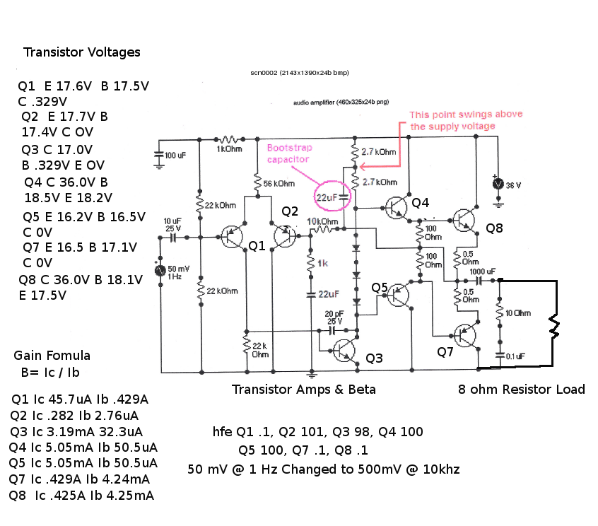
Thanks for the info, I am trying out LTSpice ASAP. The attachment is some work I did with voltages and currents and Beta. Are my firures right as the two output transistors in ProtoLab are Ideal not Tip31C &
Tip32C. You schematic put the voltages right on the money thou. I will research the link you gave me also.
Either way a new metal box with a capacitance multiplier power supply is in the near future.
-
I will check your Spice advise ASAP Thankyou. As far as useless 2.2k resistor and changing the other 2.2k to 1k and finally adding the capacitor a question arises. The construction article in G. Randy Sloans book
states that both resistors are used to keep the supply voltage at 18.0 volts at the center node to keep the voltage at emitters of Q4 & Q6 close to 18.0 volts. If that is necessary why remove the voltage devider
and raise the voltage at emitter legs? What is bootstraping as I cannot find that Termonology or definition
anywhere. Thankyou -
The schematic is a ProtoLab simulation program. Problem is the transistors are Ideal not the specified
2N3906, 2N3904, Tip31C & Tip32C. Do you know and can recomend a better simulation program where I can stipulate the correct part # and data sheet? I am askeing you because I have been following your
name for a while and like your advise. I am printing this topic and studying it to redo a plastic box in
metal till final box no hum. Thankyou -
Thankyou. I have downloaded your piece of work and will study all your posts today. One question concerning the two 100ohm resistors. Is the milliamps to the TO-92 transistors right per ohms law and data sheets? I receive different replys conserning that am trying to study the circuit with ProtoLab to figure that aspect of circuit design. The design works but with hum. The additional capacitor and 1k RC circuit are for that purpose.
A capacitance mutliplier power supply is also being designed for a revised box.


NEC Rotery Switch
in Datasheet/Parts requests
Posted
On the bottom of this switch is a metal strip and a metal button. When the switch is turned to the right the button raises upwards and then lowers. That action changes it from position A to position B.
How do I rewire this switch as it is a orirional NEC switch?