

xsumirx
-
Posts
24 -
Joined
-
Last visited
Never
Content Type
Profiles
Forums
Events
Posts posted by xsumirx
-
-
Hello,
Actually I am designing a Digital Voltmeter using ICL7107. Having capability to measure 0-200v with 0.1 resolution.
My Problem is, when I connect the output of 7805 and 7905 to ICL7107 at Pin 1 and 26
respectively. the output voltage become zero at the out pin of 7905 as well as 7805.
and not even a single 7-seg Display showing any output
Please help me !!!! :'(
I am not able to Judge weather its the Problem with my PSU or ICL7107.
I have attached my PSU ...... ??? ???
-
You may get more help if you provide a proper specification.
You also need to learn how to use Google.
http://www.google.co.uk/search?hl=en&client=opera&hs=NYc&rls=en&channel=suggest&q=SMPS%20schematic&gs_sm=3&gs_upl=14867l16551l0l16708l10l5l0l5l5l0l63l289l5l10l0&bav=on.2,or.r_gc.r_pw.,cf.osb&biw=1920&bih=927&um=1&ie=UTF-8&sa=N&tab=iw&ei=kdRIT7raIs-p0AWduemYDg
I know how to use Google
I searched too much ...but still didn't find any circuit which matches with my specification.
and I have Posted my Specification:
I need output in both negative as well positive mode
I need 5v positive as well as 5V negative (i.e; -5V)
and +10V and -10V.
If you can help me then plz post a schematic. -
Hello Friends,
Actually After Making my PSU, Today I thought to make a SMPS.
But the Problem is this I have not the schematics of the SMPS. Can anyone here Give me the schematic for designing my SMPS.
My Requirement is below
Input Range Vac(in) :- 100v to 250v
Output Vdc (out) :- +5V, -5V, +10V, -10V
With Feedback Control
Plz post your schematics here !!! I need it ;D ;D ;D ;D -
If you expect good marks then you should build it properly. I recommend calling this the first prototype then building it again more neatly.
It's not just a fire risk but a shock hazard too. The cables are so poorly soldered a live mains wire could easily break off and touch the case causing it to float at mains potential.
Where's the mains earth connection?
If you've not got one it's doubly dangerous and if you have then it could easily break off.
Both parts of the case should be connected to mains earth/ground with a longer wire than the live and neutral so it's the last to break if the mains cable is pulled out.
Where's the mains fuse?
Fine, it hopefully won't catch fire if it's working properly but what if there's a short circuit? The wires could heat up, causing smoke and fire. This is much more likely to happen as you've constructed it so poorly.
There should be a mains fuse on the primary of the transformer and it's also a good idea to put one on the secondary side too. Then if there's a short circuit it won't catch fire. In this case the fuse should be slow blow and 1.5 times the fully loaded current taken by the transformer.
Thanks Buddy.....For your Great suggestion, So, I will really work on your advice about power wiring + primary as well as secondary fuse + make the PCB more Neat and this time I gonna design it with a big chassis as it now....
Thanks buddy...again for your Great advice...... :D :D :D :D :) ;) -
Why bother making your own power supply if you do it badly? You can probably get a crappy cheap Chinese power supply off ebay for much less than it cost for all of the parts and it'll be much more reliable too.
You'll be lucky if it doesn't catch fire or electrocute you.
;D ;D ;D ;D
Don't Think Like a little baby ....Hero
I have tested it upto 4 hour of continuous in ON condition with a 500ohm of Load resistance.
Its was working fine for me
I am just using 1 amp of transformaer....but I can Handle upto 20A of current and 1 amp is nothing as compare to 20A.
Thats why Its will never catches fire at 1A
Its Just Looking like mess but I have made some fan funcation also to keep the heat sink cool.
I didn't go for ebay shop because I have to submit this project in my college as my Peoject......
I had to made this project with my hand...thats why I did not go for ebay shop.
anyway Thanks for suggestion..... !!!! :D :D :D :D :D -
Hello,
I am trying to use the LM317 part on my PSPICE 9.1 Student Version project.
I already installed the .lin and .olb, but when I run my simulation I get an
error that says "No PSpiceTemplate for U3, ignoring" (U3 is my voltage
regulator). I am assuming that its because I have not installed the Digikey
database files. It's just that I dont know how to do that.
I kindly request your help for this problem
Sorry Brother,
I have never used PSPICE, so I can't help you about pspice.....
But I will recommend you to use TINA electronics Lab....because Its having more funcation and well user Interfaced enviroments for simulation.
I am also using it ..Even I have also tested LM317 based power supply to it and simulation is also well.
Even You can add more Library file (.lib) to it.
so, I f you will go for TINA(Toolkit interactive Network analysis), I will be definetly able to help you as more as possible.
Thankyou !!! :( -
What a mess!
I know it Looks dirty and even it can let anyone in confusion.........
I can Understand...Ok anyway ....Its all just because it was my first time when I made a PSU indivisiually.... :-\ -
thankyou audio guru....I have made a power supply using LM723.....I am a beginner right now...thats why I made this simple power supply and working fine for me...
Some pics of my power supply Is here :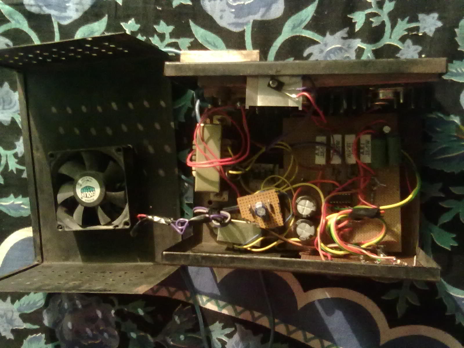
[img width=680 height=510]
[img width=680 height=510]
and finally Circuit Diagram :
[img width=680 height=466]
Hows Its -
okkk...Thanx
Tell me one more thing !!!
Will BD136 will work instead of BD140.
In power supply section -
your answer take me to 2 different confusion...
1st
if the load resistance is 20ohm , then how 40v will flow through the load, so the maximum limit of Vout is just 30v.
2nd
if the circuit will do like this then how we will get our desired Vout at the o/p end, in this manner only one thing can be controlled by us voltage or current ?
Plz... -
One thing I still did not understand..... That
Current is depend on load resistance. by changing the Load Resistance only the current can be controlled.
Can you tell me, How we are controlling the current here ?
How we get the desired current output independently to load resistance here in the circuit ?
I am completely unknown from this fact.
Plz.. ??? -
The circuit works perfectly and is very reliable.
Thankyou Audioguru :) ;D
This is that answer which I was want to listen in short :D -
:) Thanks for the tip.
I have Finally Decided to make this PS. plz tell me will it work fine as per my expectation
My requirement is 0-30v o/p
with 0-3A
Plz tell me
???
-
So, Can u Give me any modified latest schematic for power supply
My Requirement is
Variable Voltage Output = 0- 30 V
Variable Current output = 0-2/3A
Actually, I had decided to make the Circuit shown in below post :-
http://www.electronics-lab.com/projects/power/001/index.html
But, When I went to market (Lajpat Rai market, New Delhi) to purchase Component, Then I didn't found MC34072 Dual opamp.
and I stoped the project,
So, Can you Give me the any other schematic whose component are available in market or any Other IC equivalent to MC34071 -
Running under WINE is not Linux support
Its will Definetly Run under WINE.
All you have to do Just Copy the whole setup into root and then try to run it. -
The original circuit uses both opamps in each TL062 dual opamp.
But your circuit uses only one opamp in each TL062 dual opamp.
One TL064 quad opamp could also be used.
The original circuit is powered from the 9V battery at the right side of the schematic.
But your circuit has the 9V battery and the important supply bypass capacitors doing nothing because you are powering it from two 18V supplies.
Actually, The Program which I am using for simulation have TL062 in its Library with Single OP amp......Thats why I use 4 op-amp.
and The mistake which I had done in right side of my schematics......that I have modified and make it correct.
Anyway thanks for support :-* -
Thankyou...Its Really Fantastic !!!!
Finally I am Going to Design it.........Thakyou AudioGuru.
But Still I have an another problem with me......I am going to design a variable power supply 0-30v using LM723.
I am not Getting the proper output !!!
I have uploaded the Picture of my schematic !!!
Plz Help me.......
-
Thankyou Audioguru....I had done as you said....evrything is gonna fine now.........at some level Its working now...but still their is some problem,,,,....
But Dont worry.....I will solve it by my own......
Anyway thankyou.... !!!! -
Please post your schematic as a normal PNG file type so we can all see it.
I have Uploaded audioguru
Its in JPG format
-
Hello Friends,
I want to design a function Generator which can generate the frequency in audible range ( 20Hz - 20KHz). I have downloaded the schematic from a website and Now before I proceed towards my project. I want to test it on my computer using simulation program.
I am using TINA (Toolkit Interactive Network analysis) for Simulation of my schematic.
But I am Getting no output at the output end.
So, Guys I need your help to make my project possible.
Plz help me. :( :-[
I have uploaded my schematic (.TSC) please review it and give me any way to get ride over my problem. :'(
Thank you In advance. :)


+5V and -5V OUT PSU Problem !!!!
in Power Electronics
Posted
If I have done any Mistake with my Power Supply.. Then can you Please Figure it out !!!! ??? ???
and I have also attested the Schematics of the Digital voltmeter
??? ??? ???