Schorsch
-
Posts
1 -
Joined
-
Last visited
Schorsch's Achievements
")
Newbie (1/14)
0
Reputation
-
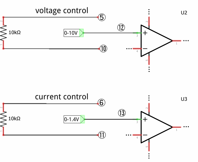
Hi, I've been working on replacing the two 10k potentiometers for voltage and current control with two rotary encoders. The idea is to get (theoretically) arbitrarily fine control via software on an ATMega328P microcontroller. The microcontroller would also be in charge of outputting desired and measured voltage and current values to an LCD. Since I haven't found any suitable digital potentiometers I figured I'd simply generate the analog voltages for the non-inverting inputs of U2 and U3. U2 gets a voltage between 0 and 10V using the uC's PWM output, a low pass filter and an op amp. Points 5 and 10 are connected with a 10k resistor. This part is working brilliantly so far. However current limit control is giving me some trouble. Again points 6 and 11 are connected with a 10k resistor and the non-inverting input of U3 is fed with an analog voltage between 0 and 1.4V (again via PWM and low pass filter). To test the setup I shorted the outputs of the supply with my multimeter, turned up the voltage to about 10V and then slowly increased the current limit. Seemingly at random one of the following scenarios occurs: The current limit increases way too fast (the microcontroller sends the signal for .5A but the multimeter already reads 3A) The current limit increases fairly accurately as it should. The current limit gets stuck and then goes haywire at some 16A and Q4 lets the magic smoke out. Am I wrong in thinking I could generate U3's input voltage isolated from points 6 and 11? If I'm not just being stupid somewhere else my suspicion is that my approach kills some vital feedback path... I'd appreciate any input, thanks!