KrisDong
-
Posts
11 -
Joined
-
Last visited
-
Days Won
1
KrisDong's Achievements
")
Newbie (1/14)
1
Reputation
-
When developing electronic projects, the power supply is one of the most important part of whole project and there is always need of multiple output voltage power supply. This is because different sensors need different input voltage and current to run efficiently. In this scenario, a power supply which can output multiple voltages becomes very important. There are options that an engineer can use for external power supply like RPS (regulated power supply) or AC adaptors but then multiple power supplies will be needed and the whole system will become bulky. So today we will be designing a Multipurpose Power Supply. The Power Supply will be an Arduino UNO Power Supply Shield which will output multiple voltage range such as 3.3V, 5V and 12V. The Shield will be a typical Arduino UNO shield with all pins of Arduino UNO can be used along with extra pins for 3.3V, 5V, 12V and GND. Here the PCB is designed on the EasyEDA PCB Designer and manufactured by PCBgogo. Components Required LM317 – 1 Unit LM7805 – 1 Unit LED(Any Color) – 1 Unit 12V DC Barrel Jack – Unit 220Ω Resistor – 1 Unit 560Ω Resistor – 2 Units 1uF Capacitor – 2 Units 0.1uF Capacitor – 1 Unit Burg Pins(20 mm) – 52 Units Circuit Diagram The circuit diagram and schematic for Arduino Power Supply Shield is pretty simple and doesn’t contain much component placement. We will be using 12V DC Barrel Jack for main voltage input for the whole Arduino UNO Shield. The LM7805 will convert 12V to 5V output, similarly the LM317 will convert 12V to 3.3V output. LM317 is popular Voltage regulator IC can be used to build variable voltage regulator circuit. Fabricating the PCB for Arduino Power Supply Shield After making the circuit ready, it’s the time to go ahead with designing our PCB using the PCB design software. As stated earlier we are using EasyEDA PCB Designer, so we just need to convert the schematic to a PCB Board. When you convert the schematic into board, you also need to place the components in the places according to the design. After converting the schematic above to board my PCB looked like below. Assembling the PCB After the board was ordered, it reached me after some days though courier in a neatly labelled well-packed box and like always the quality of the PCB was awesome. Get the soldering kit and start placing all the components in the right pads of the PCB Board. The soldering is easy to finish as there is not much components used in this project. When the soldering is finished your board should look like below. In this Power Shield the burg pins used is of male to male 20 mm connectors. You can use Male to Female Burg pins depending upon the availability. The 20mm burg pins are suitable for Arduino Shield and fits well for on Arduino UNO. Testing the Power Supply Arduino Shield It is really easy to test the Arduino shield. Just place the shield on to the Arduino UNO and give it a 12V supply from the input barrel jack. The shield can take input voltage of maximum up to 34V without damaging the components. You can check all the output voltage i.e. 3.3V, 5V and 12V using a digital multimeter. If all went good including designing and soldering of the components then you will be able to note down the exact output voltage at the output pins.
-
 dorrismillerrr123 reacted to a post in a topic:
PCBGOGO after-sale service review
dorrismillerrr123 reacted to a post in a topic:
PCBGOGO after-sale service review
-
Every digital clock has a crystal inside it to keep track of time. This crystal is not only present in the clock but also present in all computing real-time systems. This crystal generates clock pulses, which is needed for timing calculations. Although there are some other ways to get clock pulses for higher accuracy and frequency, but the most preferred way is to use crystal to keep track of time. Here we will DS3231 RTC IC to build an Atmega16 based Digital Wall Clock. DS3231 RTC has a highly accurate crystal inside it, so no external Crystal oscillator is needed. In this Digital Clock Project, ten common anode 7-segment displays of 0.8-inch are used to display time and date. Here seven segment displays are used to show hour, minute, date, month and year. Our PCB design also has options to display seconds and temperature, which can be displayed by adding more display units. Circuit Diagram and Explanation There are two parts of this Digital Wall Clock Circuit, one is display part which has 5 pairs of 7-segments on five different PCB boards and another is controlled Unit part which is responsible for fetching time from RTC chip and send that data and time to 7-segment display. As we have used 10 seven segment displays so we cannot connect each display with a separate IO port. So here multiplexing technique is used to connect multiple seven segments using fewer pins of microcontroller. LED pins a,b,c,d,e,f,g,h of seven segment display is connected to PORTB of atmega16 parallel. Here we have used 10 seven segment displays so we need 10 control pins which are connected at PORTD, PORTA and PORTC. RTC DS3231 having an internal crystal is connected to PORTC’s SDA and SCL pin because this chip works on I2C communication. Interfacing method of this chip is the same as DS1307. We have used DS1307 with Arduino, Raspberry Pi and 8051 MCU. Same code can be used for both DS3231 and DS1307. For one display board, two seven segment displays and 2 LED are used. So here we have five different display boards to display Time in Hours and minute (HH-MM), and date in DD-MM-YY. PCB Design and fabrication for the Digital Clock For this Atmega16 based wall clock project, we have designed two PCBs. One is for Control unit which is used to control all the operations of the project and second part is for displaying the time and date on seven segment displays. Display part contains five pairs of 0.8 inches seven segment display. So by assembling 5 pieces we have the complete Digital Clock. To multiplex 7-segment displays, Data line of the 5 PCBs will be connected to the same port of control unit and control line is connected different pin of the control unit. Below are the top and bottom views of PCB layouts of one Display board which consists two seven segment displays: Below are the top and bottom views of Control Unit PCBs Ordering the PCB using PCBGoGo There are many PCB fabrication services are available online, but as I used PCBGoGo previously in one of my other projects, I found it cheap and hassle-free as compared to other vendors. Here are the steps to order PCB from PCBGoGo: Step 1: Get into www.pcbgogo.com, sign up if this is your first time. Then, in the PCB Prototype tab enter the dimensions of your PCB, the number of layers and the number of PCB you require. Step 2: Proceed by clicking on the Quote Now button. You will be taken to a page where to set few additional parameters if required like the material used track spacing etc. But mostly the default values will work fine. The only thing that we have to consider here is the price and time. As you can see the Build Time is only 2-3 days and it just costs only $5 for our PSB. You can then select a preferred shipping method based on your requirement. Step 3: The final step is to upload the Gerber file and proceed with the payment. To make sure the process is smooth PCBGOGO verifies if your Gerber file is valid before proceeding with the payment. This way you can sure that your PCB is fabrication friendly and will reach you as committed. Now PCBGoGo will take some time around 10 min to 1 Hour to review your Gerber file. After completion of the review, you can proceed with the payment. Assembling the PCB After the board was ordered, it reached me after some days though courier in a neatly labeled well packed box and like always the quality of the PCB was awesome. I am sharing few pictures of the boards below for you to judge. I turned on my soldering rod and started assembling the Board. Since the Footprints, pads, vias and silkscreen are perfectly of the right shape and size I had no problem assembling the board. The board was ready in just 10 minutes from the time of unpacking the box. Few pictures of the board after soldering are shown below. Testing the Digital Clock Complete code is given at the end of this tutorial, just connect the PCBs as shown in the circuit diagram and upload the code into Atmega16. And you will see time and date appearing on the ten Seven segments displays.
-
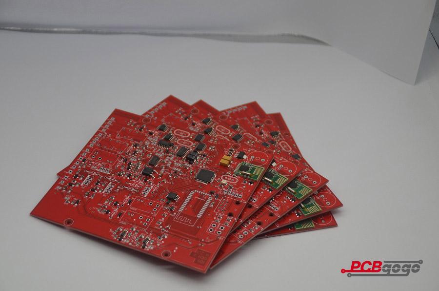
The board is made very precisely, it's clean and very pleasant to touch. Markings on the silkscreen layer are very good readable. Soldering does not cause trouble, tin adheres very well to soldering points with a small amount of flux. It is also worth mentioning that the PCB is very robust to desoldering. The company is very solid, although you order 10 pieces, you get at least 1 PCB more for test, prototype, present, etc. When I signed up for an account, I also got a $20 coupon for free. Excellent construction and assembly work done by PCBgogo.No problems encountered, highly recommended.
-
- 1
-
-
- pcb
- pcb prototype
- (and 1 more)
-
PCB manufacturing sites - work in progress
KrisDong replied to Elcpoppy's topic in Sell/Buy electronics - Job offer/requests
PCBGOGO not only in quick-turn PCB prototype and PCB assembly, but also medium and small volume PCB fabrication. We have three factories, established over 17,000 square meters; fully compliant with the ISO 9001:2008 quality management system, UL certified and committed to adhering to the strictest standards in manufacture and assembly. Advantages of PCBGOGO: Offer low cost with high quality PCB prototype and PCB assembly service, minimum order is 5 pieces. Product quality guaranteed. PCBGOGO is fully compliant with the ISO 9001:2008 quality management system and our company is UL certified. All of the circuit boards will be tested well before being shipped out. Instant online quote. Our price structure is transparent and has no hidden cost, you will know where your money is going. PCB build time as fast as 2-3 days and can provide express 12 hours & 24 hours service if your project is urgent. Various shipping methods are available for you to choose from such as DHL, UPS, EMS, FedEx and HK post. You can track your PCB and assembly order status online. You will be updated on the PCB manufacturing process and the shipping status of your order regularly. -
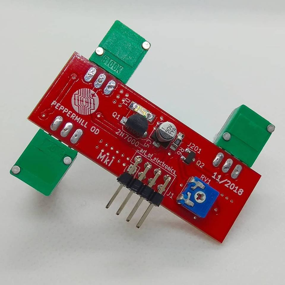
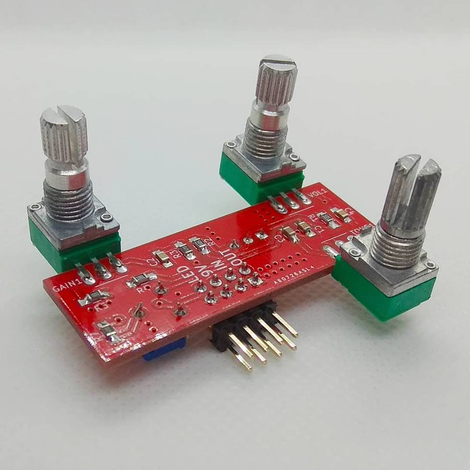
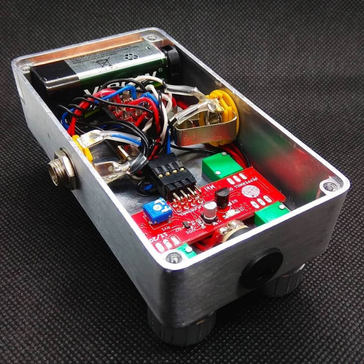
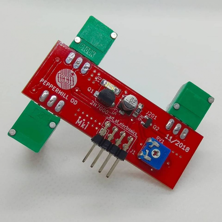
Hello guys, Another 1590B marvelous pedal effect - the peppermill overdrive (original concept found on #runoffgroove ). Looks pretty much the same as CMOS Fuzz (minimalistic raw metal design) but shines red instead of blue. In case someone is wondering I'm not changing my main coure from electronics to guitar effects. I just decided to combine three of my passions (electronics, guitar, CAD/diy) and show some new type content along with mechateonics engineers flexibility. I'll be back with some hardcore electronics content as soon as I manage to overcome some communication issues. pcb from: PCBGOGO
H8JK02UZ4773AQ7LB3.thumb.png.751f02586bea855db953ce0a444fbbbe.png)

-
I ordered some PCBs at PCBGOGO. They are a manufacturer of small and medium-sized batches in China. I received the board on the third day after I placed the order. To be honest, this's very fast.And they also have “Turnkey” service. https://www.pcbgogo.com?code=t
-
I've been working on metronome based on the Atmega328P and the Arduino language, although using a discreet microcontroller chip. It has six high brightness LEDs to indicate the beats, a buzzer, OLED display, some push buttons to control the thing, some more indicator LEDs and a 3,7 V LiPo battery with a 3.3 V voltage regulator, a charging controller and a micro USB port for charging. Before having the first prototype manufactured, if anyone could comment on what I've made so far I'd be very grateful. My aim was to make the whole thing quite small, so I've gone mostly SMD (0603 for capacitors and resistors, 1206 for LEDs). The important thing for me is the visibility of the beat LEDs (D3...D8), so I may still exchange them for 3 mm though-hole LEDs. Some of the components are hidden under the display, but they're all on the front side of the board; the only thing on the back is the battery and a ground plane. I'll be ordering the PCBs from PCBGOGO and soldering the components by hand. Images of the schematic and the PCB layout. PDF of the schematic. ZIP package of the gerber files. Thank you! Edit: One thing I'm especially unsure about is whether I have enough bypass caps around the microcontroller and if they're correctly sized and placed. What I have is mostly copied from the Arduino Nano schematic.
-
Hello, I've been working on designing a custom PCB for a custom mech keyboard, and I have no clue if I did it right. I have zero experience doing anything like this, and worked following a guide online mostly. Did I wire it correctly, even if it is messy? Did I do some really big mistake? Here are schematics and pictures, and I'll figure out a way to upload my KiCad files here, if that's allowed: https://imgur.com/a/TpA6d64 KiCad Files!
-
Since the sensor could indicate the geo-graphic North, South, East and West, we humans could also use it at times when required. So in this article let us try to understand how Magnetometer sensor works and how to interface it with a microcontroller like Arduino. Here we will build a cool Digital Compass which will help us in finding the directions by glowing an LED pointing North Direction. This Digital Compass is neatly fabricated on PCB from PCBGOGO, so that I can carry it next time when I go out in the wild and wish that I would get lost just to use this thing for finding my way back home. Materials Required Arduino Pro mini HMC5883L Magnetometer sensor LED lights - 8Nos 470Ohm Resistor – 8Nos Barrel Jack A reliable PCB manufacturer like PCBGOGO FTDI Programmer for mini PC/Laptop What is a Magnetometer and How does it Work? Before we dive into the circuit, let’s understand a bit about magnetometer and how they work. As the name suggests the term Magneto does not refer to that crazy mutant in marvel who could control metals by just playing piano in the air. Ohh! But I like that guy he is cool. Magnetometer is actually a piece of equipment that could sense the magnetic poles of the earth and point the direction according to that. We all know that Earth is huge piece of spherical magnet with North Pole and South Pole. And there is magnetic field because of it. A Magnetometer senses this magnetic field and based on the direction of the magnetic field it can detect the direction we are facing. How the HMC5883L Sensor Module Works The HMC5883L being a magnetometer sensor does the same thing. It has the HMC5883L IC on it which is from Honeywell. This IC has 3 magneto-resistive materials inside which are arranged in the axes x, y and z. The amount of current flowing through these materials is sensitive to the earth’s magnetic field. So by measuring the change in current flowing through these materials we can detect the change in Earth’s magnetic field. Once the change is magnetic field is absorbed the values can then be sent to any embedded controller like a microcontroller or processor through the I2C protocol. Since the sensor works by sensing the magnetic field, the output values will be greatly affected if a metal is placed nearby. This behavior can be leveraged to use these sensors as metal detectors also. Care should be taken not to bring magnets near this sensor since the strong magnetic field from a magnet might trigger false values on the sensor. Circuit Diagram The circuit for this Arduino based Digital Compass is pretty simple, we simply have to interface the HMC5883L sensor with the Arduino and connect 8 LEDs to the GPIO pins of the Arduino Pro mini. The complete circuit diagram is shown below The Sensor module has 5 pins out of which the DRDY (Data Ready) is not used in our project since we are operating the sensor in continuous mode. The Vcc and ground pin is used to power the Module with 5V from the Arduino board. The SCL and SDA are the I2C communication bus lines that are connected to the A4 and A5 I2C pins of the Arduino Pro mini respectively. Since the module itself has a pull high resistor on the lines, there is no need to add them externally. To indicate the direction we have used 8 LEDs all of which are connected to the GPIO pins of the Arduino through a current limiting resistor of 470 Ohms. The Complete circuit is powered by a 9V battery through the barrel Jack. This 9V is provided directly to the Vin pin of the Arduino where it is regulated to 5V using the on-board regulator on Arduino. This 5V is then used to power the sensor and the Arduino as well. Fabricating the PCBs for the Digital Compass The idea of the circuit is place the 8 LEDs in a circular fashion so that each Led points all the 8 directions namely North, North-East, East, South-East, South, South-West, West and North West respectively. So it is not easy to arrange them neatly on a breadboard or even on a perf board for that matter. Developing a PCB for this circuit will make it look more neat and easy to use. So I opened my PCB designing software and placed the LEDs and resistor in a neat circular pattern and connected the tracks to form the connections. My Design looked something like this below when completed. You can also download the Gerber file form the link given. I have designed it to be a double side board since I want the Arduino to be in the bottom side of my PCB so that it does not spoil the look on top of my PCB. If you are worrying that you have to pay high for a double side PCB then hold on I got good new coming. Now, that our Design is ready it is time to get them fabricated. To get the PCB done is quite easy, simply follow the steps below Step 1: Get into https://www.pcbgogo.com?code=t, sign up if this is your first time. Then, in the PCB Prototype tab enter the dimensions of your PCB, the number of layers and the number of PCB you require. My PCB is 80cm×80cm so the tab looks like this below Step 2: Proceed by clicking on the Quote Now button. You will be taken to a page where to set few additional parameters if required like the material used track spacing etc. But mostly the default values will work fine. The only thing that we have to consider here is the price and time. As you can see the Build Time is only 2-3 days and it just costs only $5 for our PSB. You can then select a preferred shipping method based on your requirement. Step 3: The final step is to upload the Gerber file and proceed with the payment. To make sure the process is smooth PCBGOGO verifies if your Gerber file is valid before proceeding with the payment. This way you can sure that your PCB is fabrication friendly and will reach you as committed. Assembling the PCB After the board was ordered, it reached me after some days though courier in a neatly labeled well packed box and like always the quality of the PCB was awesome. I am sharing few pictures of the boards below for you to judge. I turned on my soldering rod and started assembling the Board. Since the Footprints, pads, vias and silkscreen are perfectly of the right shape and size I had no problem assembling the board. The board was ready in just 10 minutes from the time of unpacking the box. Few pictures of the board after soldering are shown below.
H8JK02UZ4773AQ7LB3.png.eb71f96843ada95e3bfe3eea4f665124.png)