Kerrowman
-
Posts
54 -
Joined
-
Last visited
Content Type
Profiles
Forums
Events
Everything posted by Kerrowman
-

Detecting Resonance in an Electrolysis System
Kerrowman replied to Kerrowman's topic in Inventive/New Ideas
I've just run a Spice simulation and it seems, surprisingly, that the resonant frequency between points A & D is unaffected by having L3, the secondary of a transformer, in place. I had set the inductance of that coil at 3mH and being in parallel I thought it would have some effect but apparently not. While it's true that L3 would not be driven directly by the voltage source, but via induction from a primary winding, I doubt that would change this situation. JulesA.thumb.jpg.78a736c710ae929ec36580406e80a4cb.jpg)
B.thumb.jpg.02eada7862d8da7f843a28a2ea8e5109.jpg)
-
Detecting Resonance in an Electrolysis System
Kerrowman replied to Kerrowman's topic in Inventive/New Ideas
I'm assuming that resonance will still occur but, due to the extra inductance of the transformer secondary, it will be at a lower frequency (see attached). I will mock it up in LTSpice and see what happens. If that's ok then I will put some components together in the new year. The purpose of resonance is not to determine fluid level, which can be done with a simple float detector, but rather to make the most of the energy input in building up a high voltage across the electrodes. This method of electrolysis relies of the breakdown of the water dielectric while at the same time limiting current flow so, rather than just supplying electrons to produce the splitting reaction, it causes ionisation to split the water. This is the approach of the late Stan Meyer, and which many are working on to refine based on his now lapsed patents, and given that he died just before he was to release his direct water injectors for car use. His method aside, improving the efficiency of H2 production is highly topical in the drive to make the overall cost of using Hydrogen comparable with battery technology. This is only one small part of that overall movement. In case you are interested I attach a technical brief of some of his work. The Birth of New Technology - S.Meyer.pdf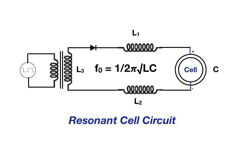
-
Detecting Resonance in an Electrolysis System
Kerrowman replied to Kerrowman's topic in Inventive/New Ideas
Thanks for the suggestion. I have had another from an outside source which suggests that, if there was a transformer in the chain, then I could wrap some turns around the secondary as a detection coil and feed this coil to the comparator. At resonance this would detect a pulse? I have draw this up in the attached which shows some of the already built components. Do you think that might work?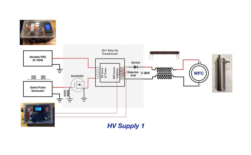
-
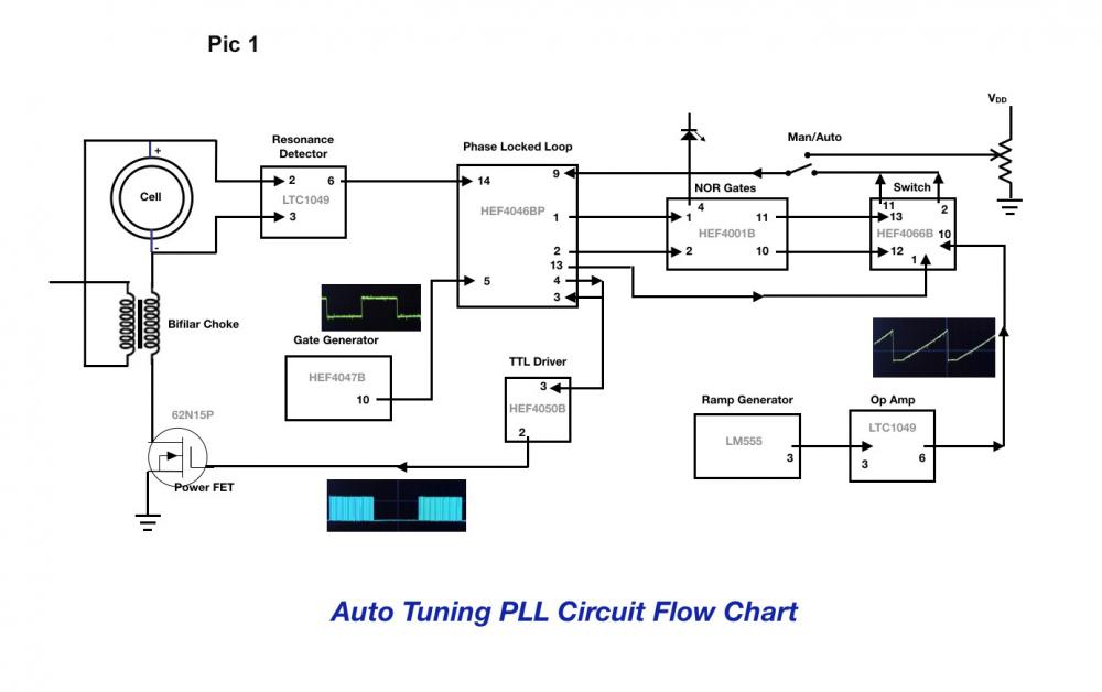
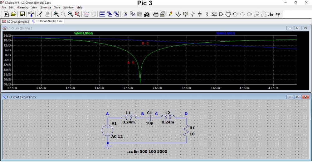
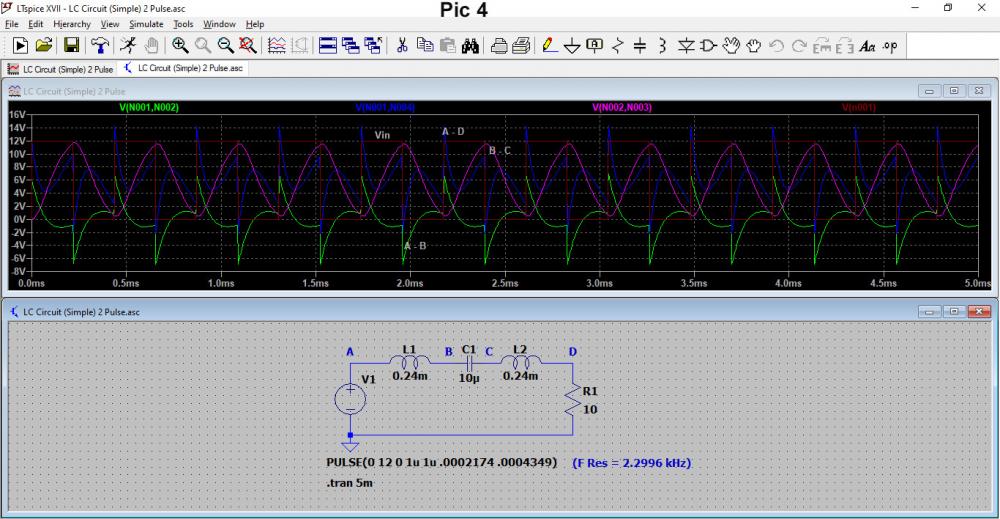
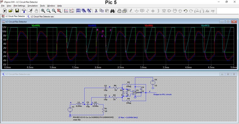
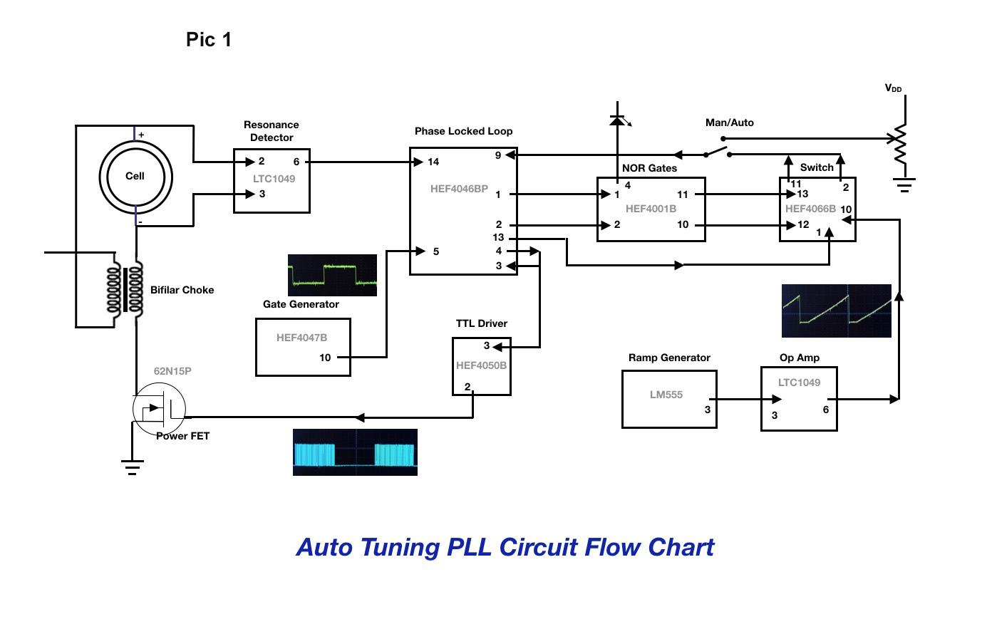
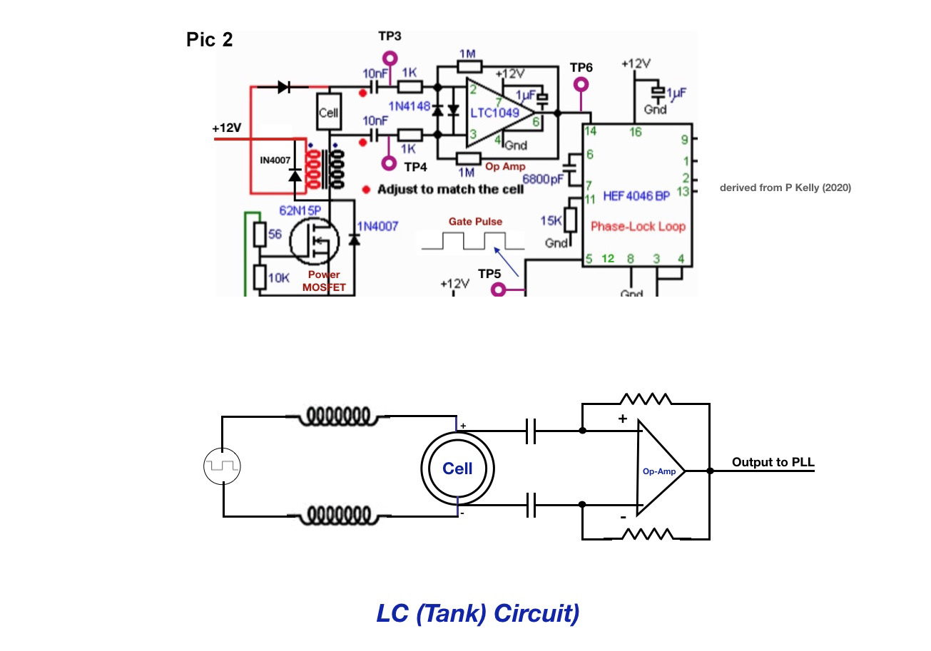
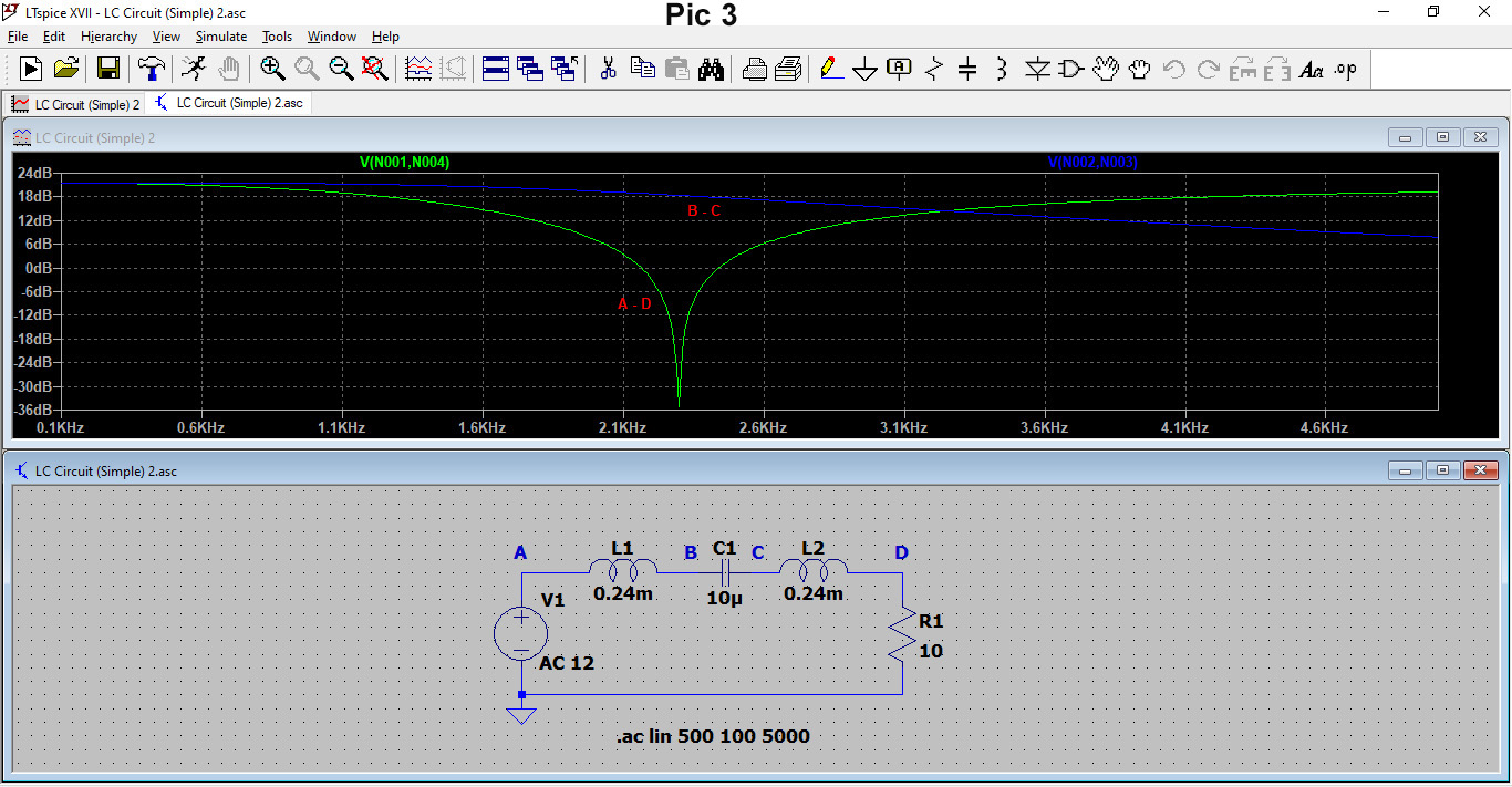
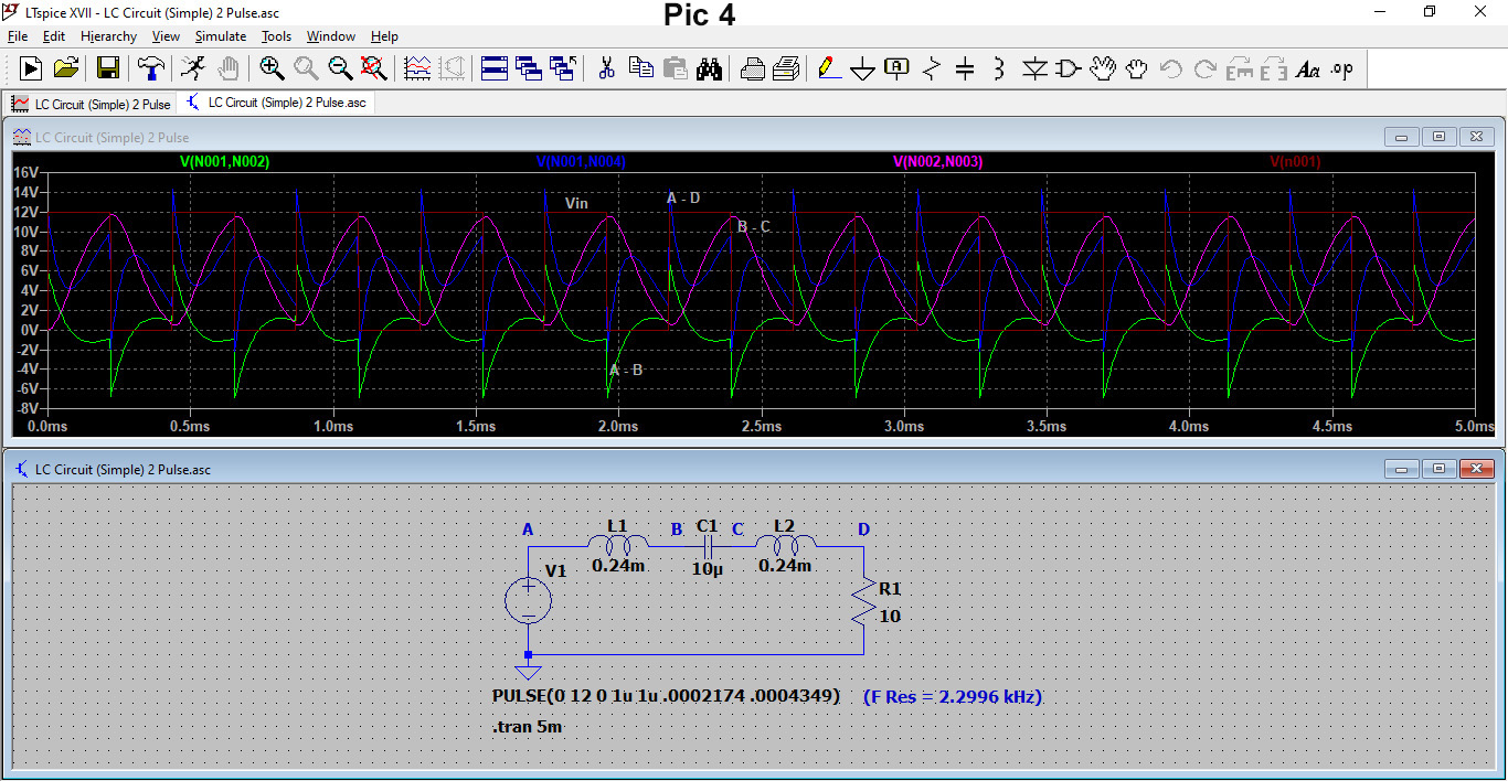
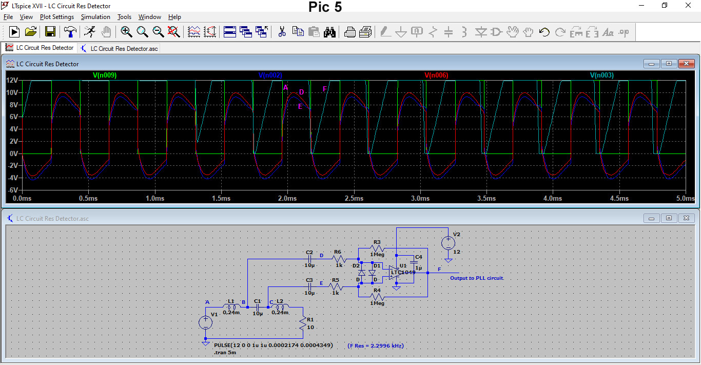
Hi there, I would like some help with finding an effective way to detect resonance in an electrolysis setup that functions like an LC circuit. Let me lay out the full context and details. (The pics are not showing in the post in this order.) Pic 1 shows the flow chart for the setup that is built and based on an auto-tuning circuit designed by a friend, who is no longer working in this area, and is designed to help explore ways to improve the efficiency of Hydrogen production. At this stage, the two gases are not separated but that doesn't affect the way the pulsed supply affects the electrolysis reaction. The small test cell uses pure water and so operates like a capacitor and, with a choke either side, can be modelled like an LC tank circuit. Part of the aim is to cause dielectric breakdown of the pure water to split it at high voltage but very low current. Pic 2 shows part of the circuit drawing that is related to detecting when resonance occurs in the cell and two chokes and which is the focus of my query. Pic 3 shows this modelled using LTSpice and that, when using typical values for L and C and a sine wave input, a resonant frequency occurs at 2.2996kHz. Pic 4 this shows what happens in the LC circuit when using a square wave input that is actually used for the electrolysis. Unlike when using a sine wave, at resonance, there does not seem to be a minimum impedance point that could be used to feed to a comparator. Pic 5 shows the LC circuit modelled with the 'Resonance Detector' op-amp setup. The various traces are the square wave input (Green), inputs to the op-amp D, E (Red, Blue) that come from across the cell (Capacitor C1) and output F (Cyan) from the op-amp. Now let me explain what happens in practice. The PLL circuit works fine (some of the traces are shown in Pic 1) on manual and where the frequency output is determined by the pot at the top right. However, on Auto, where the ramp generator results in a range of frequencies (0-20kHz) in the PLL's VCO, no output comes from the PLL chip (Pin 4). At the moment I am thinking that the PLL output may only appear in Auto mode when a resonance lock is made, but to fully understand how that lock arises I have been examining exactly what happens at resonance and how the circuit will detect it and feed a signal into Pin 14 of the PLL. From my modelling with LTSpice, I can't see any particular feature at resonance across the capacitor (cell) that could be useful to tell the op-amp that resonance is taking place, especially with a square wave input. At least with a sine wave, I could have used the voltage across the whole circuit (L-C-L) to give me a definitive low value. So to summarise my query, can I detect resonance with the current setup and pick off points or will some modest adjustment make that possible? Alternatively, perhaps I need to build some additional circuitry to enable this? Ideas welcomed. Thank you