

CETECH
-
Posts
32 -
Joined
-
Last visited
-
Days Won
2
Content Type
Profiles
Forums
Events
Everything posted by CETECH
-
In this blog, I will show you how to integrate an ultra-sonic sensor with ESPHome in home assistant. An ultra sonic sensor is a device that can measure the distance to an object by sending and receiving sound waves. It can be used for various applications, such as obstacle detection, level measurement, parking sensors, etc. What is ESPHome and Home Assistant? ESPHome is a system that allows you to easily create and manage custom firmware for ESP8266 and ESP32 devices. It uses a simple configuration file that defines the components and sensors you want to use and generates the code and binary files for you. You can then upload the firmware to your device using a USB cable or over-the-air (OTA) updates. Home Assistant is an open-source platform that allows you to control and automate your smart home devices. It supports hundreds of integrations with different services and devices, such as lights, switches, sensors, cameras, media players, etc. You can access and control your home assistant from a web browser, a mobile app, or a voice assistant. ESPHome and Home Assistant work very well together, as they can communicate with each other using the native API. This means that you can easily add your ESPHome devices to your home assistant without any extra configuration or coding. You can also use home assistant to monitor and control your ESPHome devices, and create automations based on their states and events. How to Integrate Ultra Sonic Sensor with ESPHome in Home Assistant To integrate an ultra-sonic sensor with ESPHome in home assistant, you will need the following: An ESP8266 or ESP32 device, such as NodeMCU, Wemos D1 Mini, or Xiao ESP32 S3 Sense An ultra sonic sensor, such as HC-SR04 A breadboard and some jumper wires A computer with ESPHome and Home Assistant installed. Get PCBs for Your Projects Manufactured You must check out PCBWAY for ordering PCBs online for cheap! You get 10 good-quality PCBs manufactured and shipped to your doorstep for cheap. You will also get a discount on shipping on your first order. Upload your Gerber files onto PCBWAY to get them manufactured with good quality and quick turnaround time. PCBWay now could provide a complete product solution, from design to enclosure production. Check out their online Gerber viewer function. With reward points, you can get free stuff from their gift shop. Also, check out this useful blog on PCBWay Plugin for KiCad from here. Using this plugin, you can directly order PCBs in just one click after completing your design in KiCad. Let's start with hardware the setup Connect the ultra-sonic sensor to your ESP device using the breadboard and jumper wires. The wiring diagram is shown below: Connect VCC to 5V and GND to Gnd and Trigger to pin 0 and ECHO to pin 1. Home Assistant Setup Next, navigate to the Home Assistant and open the ESPHome. Next, select one of your ESP devices or create a new one. In this case I'm going to use my existing device. Open the yaml file and add these following. sensor: - platform: ultrasonic trigger_pin: 0 echo_pin: 1 name: "Ultrasonic Sensor" update_interval: 2s Then next, click install. and choose your prefer method. I'm going to use wirelessly. Because my device is already connected with my network. Wait until it finishes the upload. Then navigate to the device property and here you can see the Sensor measurement. Next, add the measurement to the dashboard. Conclusion In this blog, I have shown you how to integrate an ultra-sonic sensor with ESPHome in home assistant. This is a simple and effective way to use an ultra-sonic sensor in your smart home projects. You can also use other types of sensors and components with ESPHome and home assistant and create your own custom firmware and integrations. I hope you found this blog helpful and informative. If you have any questions or feedback, please leave a comment below. Thank you for reading!
- 1 reply
-
- 1
-

-
In this blog, I will show you how to set a static IP address on Xiao ESP32 S3 Sense, a tiny but powerful microcontroller board with Wi-Fi and Bluetooth capabilities. Setting a static IP address can be useful if you want to access your ESP32 web server or other network services using the same IP address, even after restarting the board. What is a Static IP Address? An IP address is a unique identifier for a device on a network. It consists of four numbers separated by dots, such as 192.168.1.100. A static IP address is an IP address that does not change, unlike a dynamic IP address that is assigned by a router or a DHCP server. Advantages Easier to remember and access. More reliable and stable connection Less prone to IP conflicts or errors Disadvantages More difficult to configure and maintain. Less flexible and scalable More vulnerable to security risks Therefore, you should only use a static IP address if you have a specific need for it, and if you are aware of the potential drawbacks. Get PCBs for Your Projects Manufactured You must check out PCBWAY for ordering PCBs online for cheap! You get 10 good-quality PCBs manufactured and shipped to your doorstep for cheap. You will also get a discount on shipping on your first order. Upload your Gerber files onto PCBWAY to get them manufactured with good quality and quick turnaround time. PCBWay now could provide a complete product solution, from design to enclosure production. Check out their online Gerber viewer function. With reward points, you can get free stuff from their gift shop. Also, check out this useful blog on PCBWay Plugin for KiCad from here. Using this plugin, you can directly order PCBs in just one click after completing your design in KiCad. How to Set a Static IP Address on Xiao ESP32 S3 Sense To set a static IP address on Xiao ESP32 S3 Sense, you will need the following: A Xiao ESP32 S3 Sense board A micro-USB cable. A computer with Arduino IDE installed. A Wi-Fi network with internet access The steps are as follows: Connect the Xiao ESP32 S3 Sense board to your computer using the micro-USB cable. Open the Arduino IDE and select the correct board and port from the Tools menu. Obtain the current network settings of your ESP32 board by uploading the following sketch. Before uploading, make sure to replace the ssid and password variables with your actual Wi-Fi network credentials. #include <WiFi.h> const char* ssid = "YourNetworkName"; const char* password = "YourPassword"; void setup() { Serial.begin(115200); Serial.print("Connecting to "); Serial.println(ssid); WiFi.begin(ssid, password); while (WiFi.status() != WL_CONNECTED) { delay(1000); Serial.print("."); } Serial.println(""); Serial.println("Connected..!"); Serial.print("Current ESP32 IP: "); Serial.println(WiFi.localIP()); Serial.print("Gateway (router) IP: "); Serial.println(WiFi.gatewayIP()); Serial.print("Subnet Mask: " ); Serial.println(WiFi.subnetMask()); Serial.print("Primary DNS: "); Serial.println(WiFi.dnsIP(0)); Serial.print("Secondary DNS: "); Serial.println(WiFi.dnsIP(1)); } void loop() { } System Response Open the Serial Monitor and set the baud rate to 115200. Then, press the EN button on the ESP32 board. It may take a few moments to connect to your network, after which it will print the current network settings of the ESP32 board to the serial monitor. Take note of these settings, especially the IP address, gateway, subnet mask, and DNS servers. Choose a static IP address for your ESP32 board that is within the same subnet as your router but does not conflict with any other devices on your network. For example, if your router’s IP address is 192.168.1.1 and your subnet mask is 255.255.255.0, you can choose any IP address from 192.168.1.2 to 192.168.1.254, as long as it is not already taken by another device. You can check the IP addresses of other devices on your network using tools such as Fing or Advanced IP Scanner. Modify the previous sketch by adding the following lines before the WiFi.begin() function. Replace the staticIP, gateway, subnet, primaryDNS, and secondaryDNS variables with your chosen static IP address and the network settings you obtained in step 4. // Static IP configuration IPAddress staticIP(192, 168, 1, 100); // ESP32 static IP IPAddress gateway(192, 168, 1, 1); // IP Address of your network gateway (router) IPAddress subnet(255, 255, 255, 0); // Subnet mask IPAddress primaryDNS(192, 168, 1, 1); // Primary DNS (optional) IPAddress secondaryDNS(0, 0, 0, 0); // Secondary DNS (optional) // Configures static IP address if (!WiFi.config(staticIP, gateway, subnet, primaryDNS, secondaryDNS)) { Serial.println("STA Failed to configure"); } Upload the modified sketch to your ESP32 board and open the Serial Monitor again. You should see that your ESP32 board has successfully connected to your network using the static IP address you specified. You can now access your ESP32 web server or other network services using the static IP address. For example, if you have uploaded the ESP32 Web Server example sketch, you can open a web browser and type the static IP address in the address bar. You should see the web page that allows you to control the GPIO pins of your ESP32 board. Home Assistance with ESP32 Cam Apart from controlling the LED's we can implement this on ESP32 Cam Webserver. Now you can use the static IP in the home assistance. Add you can stream your camera footage. #include "esp_camera.h" #include <WiFi.h> // // WARNING!!! PSRAM IC required for UXGA resolution and high JPEG quality // Ensure ESP32 Wrover Module or other board with PSRAM is selected // Partial images will be transmitted if image exceeds buffer size // // You must select partition scheme from the board menu that has at least 3MB APP space. // Face Recognition is DISABLED for ESP32 and ESP32-S2, because it takes up from 15 // seconds to process single frame. Face Detection is ENABLED if PSRAM is enabled as well // =================== // Select camera model // =================== //#define CAMERA_MODEL_WROVER_KIT // Has PSRAM //#define CAMERA_MODEL_ESP_EYE // Has PSRAM //#define CAMERA_MODEL_ESP32S3_EYE // Has PSRAM //#define CAMERA_MODEL_M5STACK_PSRAM // Has PSRAM //#define CAMERA_MODEL_M5STACK_V2_PSRAM // M5Camera version B Has PSRAM //#define CAMERA_MODEL_M5STACK_WIDE // Has PSRAM //#define CAMERA_MODEL_M5STACK_ESP32CAM // No PSRAM //#define CAMERA_MODEL_M5STACK_UNITCAM // No PSRAM //#define CAMERA_MODEL_AI_THINKER // Has PSRAM //#define CAMERA_MODEL_TTGO_T_JOURNAL // No PSRAM #define CAMERA_MODEL_XIAO_ESP32S3 // Has PSRAM // ** Espressif Internal Boards ** //#define CAMERA_MODEL_ESP32_CAM_BOARD //#define CAMERA_MODEL_ESP32S2_CAM_BOARD //#define CAMERA_MODEL_ESP32S3_CAM_LCD //#define CAMERA_MODEL_DFRobot_FireBeetle2_ESP32S3 // Has PSRAM //#define CAMERA_MODEL_DFRobot_Romeo_ESP32S3 // Has PSRAM #include "camera_pins.h" // =========================== // Enter your WiFi credentials // =========================== // Replace with your network credentials const char* ssid = "xxxxxxx"; const char* password = "xxxxxxx"; // Set web server port number to 80 WiFiServer server(80); // Variable to store the HTTP request String header; // Set your Static IP address IPAddress local_IP(192, 168, 1, 162); // Set your Gateway IP address IPAddress gateway(192, 168, 1, 1); IPAddress subnet(255, 255, 0, 0); IPAddress primaryDNS(8, 8, 8, 8); //optional IPAddress secondaryDNS(8, 8, 4, 4); //optional void startCameraServer(); void setupLedFlash(int pin); void setup() { Serial.begin(115200); Serial.setDebugOutput(true); Serial.println(); camera_config_t config; config.ledc_channel = LEDC_CHANNEL_0; config.ledc_timer = LEDC_TIMER_0; config.pin_d0 = Y2_GPIO_NUM; config.pin_d1 = Y3_GPIO_NUM; config.pin_d2 = Y4_GPIO_NUM; config.pin_d3 = Y5_GPIO_NUM; config.pin_d4 = Y6_GPIO_NUM; config.pin_d5 = Y7_GPIO_NUM; config.pin_d6 = Y8_GPIO_NUM; config.pin_d7 = Y9_GPIO_NUM; config.pin_xclk = XCLK_GPIO_NUM; config.pin_pclk = PCLK_GPIO_NUM; config.pin_vsync = VSYNC_GPIO_NUM; config.pin_href = HREF_GPIO_NUM; config.pin_sccb_sda = SIOD_GPIO_NUM; config.pin_sccb_scl = SIOC_GPIO_NUM; config.pin_pwdn = PWDN_GPIO_NUM; config.pin_reset = RESET_GPIO_NUM; config.xclk_freq_hz = 20000000; config.frame_size = FRAMESIZE_UXGA; config.pixel_format = PIXFORMAT_JPEG; // for streaming //config.pixel_format = PIXFORMAT_RGB565; // for face detection/recognition config.grab_mode = CAMERA_GRAB_WHEN_EMPTY; config.fb_location = CAMERA_FB_IN_PSRAM; config.jpeg_quality = 12; config.fb_count = 1; // if PSRAM IC present, init with UXGA resolution and higher JPEG quality // for larger pre-allocated frame buffer. if(config.pixel_format == PIXFORMAT_JPEG){ if(psramFound()){ config.jpeg_quality = 10; config.fb_count = 2; config.grab_mode = CAMERA_GRAB_LATEST; } else { // Limit the frame size when PSRAM is not available config.frame_size = FRAMESIZE_SVGA; config.fb_location = CAMERA_FB_IN_DRAM; } } else { // Best option for face detection/recognition config.frame_size = FRAMESIZE_240X240; #if CONFIG_IDF_TARGET_ESP32S3 config.fb_count = 2; #endif } #if defined(CAMERA_MODEL_ESP_EYE) pinMode(13, INPUT_PULLUP); pinMode(14, INPUT_PULLUP); #endif // camera init esp_err_t err = esp_camera_init(&config); if (err != ESP_OK) { Serial.printf("Camera init failed with error 0x%x", err); return; } sensor_t * s = esp_camera_sensor_get(); // initial sensors are flipped vertically and colors are a bit saturated if (s->id.PID == OV3660_PID) { s->set_vflip(s, 1); // flip it back s->set_brightness(s, 1); // up the brightness just a bit s->set_saturation(s, -2); // lower the saturation } // drop down frame size for higher initial frame rate if(config.pixel_format == PIXFORMAT_JPEG){ s->set_framesize(s, FRAMESIZE_QVGA); } #if defined(CAMERA_MODEL_M5STACK_WIDE) || defined(CAMERA_MODEL_M5STACK_ESP32CAM) s->set_vflip(s, 1); s->set_hmirror(s, 1); #endif #if defined(CAMERA_MODEL_ESP32S3_EYE) s->set_vflip(s, 1); #endif // Setup LED FLash if LED pin is defined in camera_pins.h #if defined(LED_GPIO_NUM) setupLedFlash(LED_GPIO_NUM); #endif // Configures static IP address if (!WiFi.config(local_IP, gateway, subnet, primaryDNS, secondaryDNS)) { Serial.println("STA Failed to configure"); } // Connect to Wi-Fi network with SSID and password Serial.print("Connecting to "); Serial.println(ssid); WiFi.begin(ssid, password); while (WiFi.status() != WL_CONNECTED) { delay(500); Serial.print("."); } // Print local IP address and start web server Serial.println(""); Serial.println("WiFi connected."); Serial.println("IP address: "); Serial.println(WiFi.localIP()); startCameraServer(); Serial.print("Camera Ready! Use 'http://"); Serial.print(WiFi.localIP()); Serial.println("' to connect"); } void loop() { // Do nothing. Everything is done in another task by the web server delay(10000); } Conclusion In this blog, I have shown you how to set a static IP address on Xiao ESP32 S3 Sense, a tiny but powerful microcontroller board with Wi-Fi and Bluetooth capabilities. Setting a static IP address can be useful if you want to access your ESP32 web server or other network services using the same IP address, even after restarting the board. However, you should also be aware of the potential disadvantages and risks of using a static IP address, and only use it if you have a specific need for it. I hope you found this blog helpful and informative. If you have any questions or feedback, please leave a comment below. Thank you for reading!
-
Streaming ESP32-CAM Video to Home Assistant The ESP32-CAM is a versatile and affordable camera module that can be used for various projects. In this tutorial, we’ll explore how to set up video streaming from the ESP32-CAM to Home Assistant, allowing you to monitor your surroundings remotely. Setting Up Video Streaming Web Server Open the Arduino IDE and navigate to the ESP32 examples. 1. Select File->Examples->ESP32->Camera->CameraWebServer example in Arduino IDE. 2. Replace the codes in CameraWebServer with the code below (Note: please fill in your WiFi account and password) #include "esp_camera.h" #include <WiFi.h> // // WARNING!!! PSRAM IC required for UXGA resolution and high JPEG quality // Ensure ESP32 Wrover Module or other board with PSRAM is selected // Partial images will be transmitted if image exceeds buffer size // // You must select partition scheme from the board menu that has at least 3MB APP space. // Face Recognition is DISABLED for ESP32 and ESP32-S2, because it takes up from 15 // seconds to process single frame. Face Detection is ENABLED if PSRAM is enabled as well // =================== // Select camera model // =================== #define PWDN_GPIO_NUM -1 #define RESET_GPIO_NUM -1 #define XCLK_GPIO_NUM 45 #define SIOD_GPIO_NUM 1 #define SIOC_GPIO_NUM 2 #define Y9_GPIO_NUM 48 #define Y8_GPIO_NUM 46 #define Y7_GPIO_NUM 8 #define Y6_GPIO_NUM 7 #define Y5_GPIO_NUM 4 #define Y4_GPIO_NUM 41 #define Y3_GPIO_NUM 40 #define Y2_GPIO_NUM 39 #define VSYNC_GPIO_NUM 6 #define HREF_GPIO_NUM 42 #define PCLK_GPIO_NUM 5 #include "DFRobot_AXP313A.h" DFRobot_AXP313A axp; // =========================== // Enter your WiFi credentials // =========================== const char* ssid = "*****"; const char* password = "******"; void startCameraServer(); void setup() { Serial.begin(115200); Serial.setDebugOutput(true); Serial.println(); while(axp.begin() != 0){ Serial.println("init error"); delay(1000); } axp.enableCameraPower(axp.eOV2640);//Enable the power for camera camera_config_t config; config.ledc_channel = LEDC_CHANNEL_0; config.ledc_timer = LEDC_TIMER_0; config.pin_d0 = Y2_GPIO_NUM; config.pin_d1 = Y3_GPIO_NUM; config.pin_d2 = Y4_GPIO_NUM; config.pin_d3 = Y5_GPIO_NUM; config.pin_d4 = Y6_GPIO_NUM; config.pin_d5 = Y7_GPIO_NUM; config.pin_d6 = Y8_GPIO_NUM; config.pin_d7 = Y9_GPIO_NUM; config.pin_xclk = XCLK_GPIO_NUM; config.pin_pclk = PCLK_GPIO_NUM; config.pin_vsync = VSYNC_GPIO_NUM; config.pin_href = HREF_GPIO_NUM; config.pin_sscb_sda = SIOD_GPIO_NUM; config.pin_sscb_scl = SIOC_GPIO_NUM; config.pin_pwdn = PWDN_GPIO_NUM; config.pin_reset = RESET_GPIO_NUM; config.xclk_freq_hz = 20000000; config.frame_size = FRAMESIZE_UXGA; config.pixel_format = PIXFORMAT_JPEG; // for streaming //config.pixel_format = PIXFORMAT_RGB565; // for face detection/recognition config.grab_mode = CAMERA_GRAB_WHEN_EMPTY; config.fb_location = CAMERA_FB_IN_PSRAM; config.jpeg_quality = 12; config.fb_count = 1; // if PSRAM IC present, init with UXGA resolution and higher JPEG quality // for larger pre-allocated frame buffer. if(config.pixel_format == PIXFORMAT_JPEG){ if(psramFound()){ config.jpeg_quality = 10; config.fb_count = 2; config.grab_mode = CAMERA_GRAB_LATEST; } else { // Limit the frame size when PSRAM is not available config.frame_size = FRAMESIZE_SVGA; config.fb_location = CAMERA_FB_IN_DRAM; } } else { // Best option for face detection/recognition config.frame_size = FRAMESIZE_240X240; #if CONFIG_IDF_TARGET_ESP32S3 config.fb_count = 2; #endif } #if defined(CAMERA_MODEL_ESP_EYE) pinMode(13, INPUT_PULLUP); pinMode(14, INPUT_PULLUP); #endif // camera init esp_err_t err = esp_camera_init(&config); if (err != ESP_OK) { Serial.printf("Camera init failed with error 0x%x", err); return; } sensor_t * s = esp_camera_sensor_get(); // initial sensors are flipped vertically and colors are a bit saturated if (s->id.PID == OV3660_PID) { s->set_vflip(s, 1); // flip it back s->set_brightness(s, 1); // up the brightness just a bit s->set_saturation(s, -2); // lower the saturation } // drop down frame size for higher initial frame rate if(config.pixel_format == PIXFORMAT_JPEG){ s->set_framesize(s, FRAMESIZE_QVGA); } #if defined(CAMERA_MODEL_M5STACK_WIDE) || defined(CAMERA_MODEL_M5STACK_ESP32CAM) s->set_vflip(s, 1); s->set_hmirror(s, 1); #endif #if defined(CAMERA_MODEL_ESP32S3_EYE) s->set_vflip(s, 1); #endif WiFi.begin(ssid, password); WiFi.setSleep(false); while (WiFi.status() != WL_CONNECTED) { delay(500); Serial.print("."); } Serial.println(""); Serial.println("WiFi connected"); startCameraServer(); Serial.print("Camera Ready! Use 'http://"); Serial.print(WiFi.localIP()); Serial.println("' to connect"); } void loop() { // Do nothing. Everything is done in another task by the web server delay(10000); } Then upload the code to the FireBeetle ESP32 S3 board and look for the serial terminal response. Get PCBs for Your Projects Manufactured You must check out PCBWAY for ordering PCBs online for cheap! You get 10 good-quality PCBs manufactured and shipped to your doorstep for cheap. You will also get a discount on shipping on your first order. Upload your Gerber files onto PCBWAY to get them manufactured with good quality and quick turnaround time. PCBWay now could provide a complete product solution, from design to enclosure production. Check out their online Gerber viewer function. With reward points, you can get free stuff from their gift shop. Also, check out this useful blog on PCBWay Plugin for KiCad from here. Using this plugin, you can directly order PCBs in just one click after completing your design in KiCad. Setting Up Video Stream Properties Next, open up the IP address that shows in the serial terminal and look for the camera web server properties. Set up the resolution. Go with the lower one to get a high FPS. Finally, add the:81/stream in the camera IP address. Now it will directly show you the camera feed. Integrating with Home Assistant Open Home Assistant. Next, navigate to the overview and add a picture card. Enter the IP address of your ESP32-CAM following:81/stream and click Finish. And that’s it! You’ve successfully set up video streaming from the ESP32-CAM to Home Assistant. Feel free to customize and enhance this project further. Happy monitoring! 📷🏠
-
This project will allow you to monitor environmental conditions in your home automation setup. Here are the steps to achieve this: Integrating DHT11 with Beetle ESP32 C3 and Home Assistant 1. Components Required Before we begin, gather the necessary components: BeetleESP32C3 development board DHT11 temperature and humidity sensor Jumper wires USB cable for programming A computer with the Arduino IDE or ESPHome installed Get PCBs for Your Projects Manufactured You must check out PCBWAY for ordering PCBs online for cheap! You get 10 good-quality PCBs manufactured and shipped to your doorstep for cheap. You will also get a discount on shipping on your first order. Upload your Gerber files onto PCBWAY to get them manufactured with good quality and quick turnaround time. PCBWay now could provide a complete product solution, from design to enclosure production. Check out their online Gerber viewer function. With reward points, you can get free stuff from their gift shop. Also, check out this useful blog on PCBWay Plugin for KiCad from here. Using this plugin, you can directly order PCBs in just one click after completing your design in KiCad. 2. Flashing ESPHome to Beetle ESP32 C3 Install ESPHome on your computer. You can follow the instructions in my previous blog. Create an ESPHome configuration file (e.g., dht11.yaml) with the following content: sensor: - platform: dht pin: 0 model: dht11 temperature: name: "Living Room Temperature" humidity: name: "Living Room Humidity" update_interval: 5 s Replace placeholders (YourWiFiSSID, YourWiFiPassword, etc.) with your actual values. Compile and upload the configuration to your Beetle ESP32 C3 using the ESPHome CLI. 3. Integrating with Home Assistant Open Home Assistant. Click on Configuration (bottom left) and go to Integrations. Click the + button and select ESPHome. Enter the IP address of your ESP32 (leave the port as 6053) and click Finish. 4. Viewing Temperature and Humidity Once integrated, Home Assistant will discover the Beetle ESP32 C3 module and create entities for temperature and humidity. You can access these entities in Home Assistant’s dashboard and display them as cards or graphs. And that’s it! You’ve successfully integrated the DHT11 sensor with your Beetle ESP32 C3 and Home Assistant. Feel free to customize and expand this project based on your needs. Happy monitoring! 🌡️💧🏠
-
In this article, will see how we can integrate the Beetle ESP32 C3 with home assistance. Beetle ESP32 C3 The Beetle ESP32-C3 is based on the ESP32-C3, a RISC-V 32-bit single-core processor. Despite its tiny size (only 25×20.5 mm), it packs a punch with up to 13 IO ports broken out, making it ideal for various projects without worrying about running out of IO options. Key Features: Ultra-Small Size: The Beetle ESP32-C3 measures just 25×20.5 mm (0.98×0.81 inch), making it perfect for space-constrained projects. Built-in Lithium Battery Charging Management: Safely charge and discharge lithium-ion batteries directly on the board. No need for additional modules, to ensure application size and safety. Easy Screen Connectivity: The matching bottom plate simplifies project assembly and screen usage. Dual-Mode Communication: Supports Wi-Fi and Bluetooth 5 (LE). Reduces networking complexity. Compatible with both Bluetooth Mesh and Espressif WiFi Mesh for stable communication and extended coverage. Get PCBs for Your Projects Manufactured You must check out PCBWAY for ordering PCBs online for cheap! You get 10 good-quality PCBs manufactured and shipped to your doorstep for cheap. You will also get a discount on shipping on your first order. Upload your Gerber files onto PCBWAY to get them manufactured with good quality and quick turnaround time. PCBWay now could provide a complete product solution, from design to enclosure production. Check out their online Gerber viewer function. With reward points, you can get free stuff from their gift shop. Also, check out this useful blog on PCBWay Plugin for KiCad from here. Using this plugin, you can directly order PCBs in just one click after completing your design in KiCad. Installing ESP Addon in Home Assistance First, we need to add the ESP addon to our Home Assistance system. Open the home assistance. Next, navigate to the settings and open the add-ons. Here selects ESP home and install it. Then open the web ui. ESPHome on the Beetle ESP32 C3 ESPHome is an open-source firmware that allows you to configure and manage your ESP devices easily. Open the ESP home web UI and add a new device. Then open the ESPHOME web and follow the instructions to flash ESP Home firmware. Next, connect Beetle to the PC and select then burn. Wait until it finishes. Next, enter the WiFi credentials to configure with WiFi. Then click visit device, you can see this kind of web page. Connecting Beetle ESP32 C3 to Home Assistant Once your FireBeetle ESP32 C3 is online with the ESPHome firmware, Home Assistant will automatically discover it. You can see the device under the settings menu. Next, open the ESP home and add a new device Then enter all the details, and next select the wireless option. You can see the device status as Online. Here you can edit the beetle behavior. Controlling Devices and Automation With the Beetle ESP32 C3 integrated into Home Assistant, you can: Control smart switches, lights, or other devices connected to your Beetle. Set up automation based on sensor data (e.g., turn on lights when motion is detected). Monitor temperature, humidity, and other environmental factors using Beetle sensors. With the Beetle ESP32 C3 integrated into Home Assistant, you can: Control smart switches, lights, or other devices connected to your Beetle. Set up automation based on sensor data (e.g., turn on lights when motion is detected). Here is the simple code snippet to control the onboard LED on the Beetle. switch: - platform: gpio name: "test_lights Onboard light" pin: 10 inverted: True restore_mode: RESTORE_DEFAULT_OFF Here is the complete sketch. Then install it. Next, open the devices again and select the esp home. Here you will see your device details and it will show the switch status. From here you can control the onboard LED. Troubleshooting and Tips If you encounter issues: Check your ESPHome configuration for errors. Verify that your Beetle ESP32 C3 is connected to the correct Wi-Fi network. Use Home Assistant’s logs and developer tools to debug any problems. Conclusion Integrating the Beetle ESP32 C3 with Home Assistant expands your smart home capabilities. Whether you’re building custom sensors, controlling lights, or automating tasks, this combination empowers you to create a personalized and efficient home environment. Happy tinkering! 🏡🔌
-
Home Assistant, an impressive platform that empowers you to control your home devices and services seamlessly. Whether you’re a tech enthusiast or simply want to enhance your living space, Home Assistant has got you covered. What Is Home Assistant? Home Assistant is an open-source home automation platform that acts as the central hub for managing your smart home. Here are some key features: Integration with Over 1000 Brands: Home Assistant plays well with a vast array of devices and services. From smart lights and thermostats to security cameras and voice assistants, it integrates seamlessly. Once you set up your devices, Home Assistant automatically scans your network and allows you to configure them easily. Powerful Automation: Imagine your home working for you! With Home Assistant’s advanced automation engine, you can create custom rules and triggers. Extendable with Add-Ons: Home Assistant isn’t limited to its core functionality. You can easily install additional applications (add-ons) to enhance your setup. Local Data Privacy: Unlike cloud-based solutions, Home Assistant keeps your data local. It communicates directly with your devices without relying on external servers. Your privacy is preserved, and no data is stored in the cloud. Companion Mobile Apps: Control your devices and receive notifications using the official Home Assistant apps. These apps also enable presence detection, allowing you to trigger automation based on your location. Rest assured, your data is sent directly to your home, with no third-party access. Installation Options: Home Assistant OS: A ready-to-use image for devices like Raspberry Pi, Odroid, or Intel NUC. Home Assistant Supervised: Install Home Assistant on a generic Linux system using Docker. Home Assistant Container: Run Home Assistant in a Docker container. Home Assistant Core: For advanced users who prefer manual installation on Python environments. By setting it up in a virtual machine, you can experiment with Home Assistant without affecting your primary Windows environment. Get PCBs for Your Projects Manufactured You must check out PCBWAY for ordering PCBs online for cheap! You get 10 good-quality PCBs manufactured and shipped to your doorstep for cheap. You will also get a discount on shipping on your first order. Upload your Gerber files onto PCBWAY to get them manufactured with good quality and quick turnaround time. PCBWay now could provide a complete product solution, from design to enclosure production. Check out their online Gerber viewer function. With reward points, you can get free stuff from their gift shop. Also, check out this useful blog on PCBWay Plugin for KiCad from here. Using this plugin, you can directly order PCBs in just one click after completing your design in KiCad. Prerequisites: Windows 11: Ensure you’re running Windows 11 on your host machine. VirtualBox: Download and install VirtualBox if you haven’t already. Installation Steps: 1. Download the Home Assistant Image: Visit the Home Assistant installation page. Under the “As a virtual appliance (x86_64/UEFI)” section, download the VirtualBox Disk Image (VDI) file. This image contains everything needed to run Home Assistant on Windows. 2. Create a Virtual Machine in VirtualBox: Open VirtualBox and click on “New” to create a new virtual machine. Choose a name for your VM (e.g., “HomeAssistant”). Select “Linux” as the type and “Other Linux (64-bit)” as the version. Allocate at least 2 GB of RAM, 32 GB of storage, and 2 vCPUs to the VM. Adjust these resources based on your needs. 3. Load the Home Assistant Image: In the VM settings, go to the “Harddisk” tab. Add a new optical drive and select the Home Assistant VDI file you downloaded. Make sure the optical drive is set as the first boot device. 4. Configure the VM: Go to the “Network” tab and ensure that the network adapter is set to “Attached to Bridged Adapter.” This allows Home Assistant to communicate with other devices on your network. Save the settings and start the VM. 5. Install Home Assistant: Observe the boot process of the Home Assistant Operating System. Once completed, you can access Home Assistant by opening a web browser and navigating to http://homeassistant.local:8123. If you encounter issues with the hostname, try accessing it via http://homeassistant:8123 or [your_VM_IP]:8123. 6. Onboarding: With Home Assistant installed, follow the onboarding process to set up your user account and configure integrations. You can also install additional add-ons and customize your smart home setup. Important Notes: Running Home Assistant Core directly on Windows is not supported. Use the Windows Subsystem for Linux (WSL) to install Home Assistant Core. The provided VDI image contains the Home Assistant Operating System, which is a lightweight and optimized environment for running Home Assistant. Remember to explore Home Assistant’s extensive documentation and community forums for further guidance and customization options. Enjoy building your smart home! 🏡
-
How to Track the ISS Location with Node-RED Node-RED is a visual programming tool that allows you to create flows of data and logic using nodes. In this article, we will use Node-RED to track the location of the International Space Station (ISS) and display it on a world map. What You Need To follow this tutorial, you will need the following: A computer with Node-RED installed. You can download and install Node-RED from here. An internet connection to access the ISS location API and the world map node. Two Node-RED nodes: node-red-contrib-iss-location and node-red-contrib-web-worldmap. You can install them from the Node-RED palette or by running the following commands in your Node-RED user directory, typically ~/.node-red: npm install node-red-contrib-web-worldmap Get PCBs for Your Projects Manufactured You must check out PCBWAY for ordering PCBs online for cheap! You get 10 good-quality PCBs manufactured and shipped to your doorstep for cheap. You will also get a discount on shipping on your first order. Upload your Gerber files onto PCBWAY to get them manufactured with good quality and quick turnaround time. PCBWay now could provide a complete product solution, from design to enclosure production. Check out their online Gerber viewer function. With reward points, you can get free stuff from their gift shop. Also, check out this useful blog on PCBWay Plugin for KiCad from here. Using this plugin, you can directly order PCBs in just one click after completing your design in KiCad. The Flow The flow we will create consists of four nodes: An inject node that triggers the flow every 10 seconds. An HTTP-request node that queries the ISS location API and returns the current latitude and longitude of the ISS. A function node that formats the location data into a message object that the world map node can use. A worldmap node that displays a world map and a marker for the ISS location. The flow looks like this: The Nodes Let’s take a closer look at each node and how to configure them. The Inject Node The inject node is used to trigger the flow at regular intervals. To configure it, double-click on it and set the following properties: Name: Every 10 seconds Repeat: interval Every: 10 seconds This will make the node send a timestamp message every 10 seconds. The HTTP Request Node The ISS location node is used to query the ISS location API and return the current latitude and longitude of the ISS. To configure it, double-click on it and set the following properties: Name: ISS Location URL: api.open-notify.org/iss-now.json This will make the node send a message object with the following properties: This node will return the following payload: the return payload contains thefollowing properties: latitude: a string indicating the current latitude of the ISS in degrees. longitude: a string indicating the current longitude of the ISS in degrees. The Function Node The function node is used to format the location data into a message object that the world map node can use. To configure it, double-click on the JSON node and set the following properties. Next, set the following properties on the change node: This will make the node send a message object with the same properties as the original message, except for the payload, which will be an object suitable for the world map node. Here is the final transformed payload that the map node can understand. The World Map Node The world map node displays a world map and a marker for the ISS location. To configure it, double-click on it and set the following properties: This will make the node display a world map widget on the dashboard, with various options to customize the view. The node will also listen for incoming messages with location data and display a marker on the map accordingly. The Result To see the result, deploy the flow and open the dashboard. You should see a world map with a blue globe icon indicating the current location of the ISS. The icon will move as the ISS orbits the Earth. You can also click on the icon to see the name and the coordinates of the ISS. Conclusion In this article, we have learned how to use Node-RED to track the location of the ISS and display it on a world map. We have used node-red-contrib-web-worldmap to query the ISS location API and display the map widget. We have also used a function node to format the location data into a message object that the world map node can use. We hope you have enjoyed this tutorial and learned something new. If you want to learn more about Node-RED and its nodes, you can check out these web pages: Node-RED node-red-contrib-iss-location (node) - Node-RED node-red-contrib-web-worldmap (node) - Node-RED Happy coding!
-
If you are a PC enthusiast, you might want to monitor the performance and status of your PC components, such as CPU, GPU, RAM, SSD, HDD, temperature, fan speed, etc. However, opening the task manager or third-party software every time you want to check this information can be inconvenient and distracting. Moreover, you might not be able to see this information when you are gaming or doing other full-screen activities. That’s why a 3.5-inch PC state display can be a great addition to your PC setup. A 3.5-inch PC state display is a small screen that can be mounted on your PC case and display various information about your PC state. It can show you the CPU model, usage, frequency, temperature, fan speed, GPU model, usage, frequency, temperature, fan speed, RAM usage, SSD/HDD usage, network speed, IP address, weather forecast, and custom information. You can also choose from different themes and orientations to suit your preferences. A 3.5-inch PC state display can help you monitor your PC state at a glance, without interrupting your workflow or gaming experience. It can also enhance the aesthetics and functionality of your PC case, making it more personalized and attractive. Whether you are a gamer, a streamer, a content creator, or a professional, a 3.5-inch PC state display can be a useful and fun tool for your PC. In this article, I will show you how to get started with a 3.5-inch PC state display, how to install it, how to customize it, and how to use it. Let’s begin! Get PCBs for Your Projects Manufactured You must check out PCBWAY for ordering PCBs online for cheap! You get 10 good-quality PCBs manufactured and shipped to your doorstep for cheap. You will also get a discount on shipping on your first order. Upload your Gerber files onto PCBWAY to get them manufactured with good quality and quick turnaround time. PCBWay now could provide a complete product solution, from design to enclosure production. Check out their online Gerber viewer function. With reward points, you can get free stuff from their gift shop. Also, check out this useful blog on PCBWay Plugin for KiCad from here. Using this plugin, you can directly order PCBs in just one click after completing your design in KiCad. Installing the Display on the PC Case The 3.5-inch PC state display comes with a metal bracket that can be attached to your PC case using screws. The bracket has four holes that match the standard 3.5-inch drive bay size. You can use the screws that came with your PC case or the display to secure the bracket to the case. Make sure the display is facing the right direction and is aligned with the bracket. Alternatively, you can use double-sided tape or Velcro to stick the display to your PC case, if you don’t want to use screws or if your case doesn’t have a 3.5-inch drive bay. You can also use a 3D-printed enclosure or a custom-made frame to mount the display on your PC case if you want to be more creative. Connecting the Display to the Motherboard or USB Port The 3.5-inch PC state display has two cables: a power cable and a data cable. The power cable has a 5-pin connector that can be plugged into the motherboard’s USB 2.0 header. The data cable has a 9-pin connector that can be plugged into the motherboard’s COM port or serial port. If your motherboard doesn’t have a COM port or serial port, you can use a 9-pin USB adapter cable to connect the data cable to a USB port. The power cable provides the power supply for the display, while the data cable provides communication between the display and the software. You need to connect both cables for the display to work properly. Downloading and Running the Software You can download the latest version of the software from the official website or the link provided in the user manual. To install the software, you need to download the software package and unzip it. Then, you need to run the setup.exe file and follow the instructions on the screen. The software will install the driver and the application for the display, and create a shortcut on your desktop. To run the software, you need to double-click the shortcut on your desktop or find the application in the start menu. The software will automatically detect the display and show the information on the screen. You can also access the settings and customization options from the software interface. Changing the Theme, Orientation, and Information The 3.5-inch PC state display comes with several themes that you can choose from to suit your preferences. You can also change the orientation of the display to portrait or landscape mode, depending on how you mount the display on your PC case. Moreover, you can customize the information that you want to see on the display, such as the CPU model, the GPU model, the network speed, etc. To change the theme, orientation, and information of the display, you need to open the software interface and click on the “Settings” button. You will see a window with different tabs and options. On the “Theme” tab, you can select the theme from the drop-down menu. You can also adjust the screen flip angle from 0 to 180 degrees. On the “Information” tab, you can check or uncheck the items that you want to display on the screen. You can also enter some custom information, such as your name or your PC name. On the “Other” tab, you can change the language, the font size, the refresh rate, and the brightness of the display. After you make your changes, you need to click on the “Save” button and restart the software for the changes to take effect Conclusion In this article, I have shown you how to get started with a 3.5-inch PC state display, how to install it, how to customize it, and how to use it. I hope you have enjoyed this tutorial and learned something new and useful. A 3.5-inch PC state display can be a great way to monitor your PC state, enhance your PC case, and have some fun.
-
In this blog post, I will show you how to create a web server with an ESP32 board that allows you to control the brightness of an LED using a slider on a web page. This is a fun and easy project demonstrating how to use the ESP32’s PWM (Pulse Width Modulation) feature to vary the intensity of an LED. You will also learn how to use the ESPAsyncWebServer and AsyncTCP libraries to handle asynchronous web requests and responses, which can improve the performance and responsiveness of your web server. What You Will Need: To follow along with this tutorial, you will need the following components: An ESP32 board (I’m using the ESP32 DevKitC) The Arduino IDE installed on your computer The ESPAsyncWebServer and AsyncTCP libraries installed on your Arduino IDE You can find the links to download the libraries and the complete code for this project at the end of this post. Get PCBs for Your Projects Manufactured You must check out PCBWAY for ordering PCBs online for cheap! You get 10 good-quality PCBs manufactured and shipped to your doorstep for cheap. You will also get a discount on shipping on your first order. Upload your Gerber files onto PCBWAY to get them manufactured with good quality and quick turnaround time. PCBWay now could provide a complete product solution, from design to enclosure production. Check out their online Gerber viewer function. With reward points, you can get free stuff from their gift shop. Also, check out this useful blog on PCBWay Plugin for KiCad from here. Using this plugin, you can directly order PCBs in just one click after completing your design in KiCad. How It Works: The basic idea of this project is to use a slider on a web page to send an HTTP request to the ESP32 with a value between 0 and 255, representing the LED's desired brightness. The ESP32 will then use that value to adjust the duty cycle of a PWM signal, which is a digital signal that switches between high and low states at a certain frequency. By changing the ratio of the high and low states, we can change the average voltage applied to the LED, and thus its brightness. The inbuilt LED is connected to GPIO2, which is one of the pins that supports PWM (Pulse Width Modulation). PWM is a technique that allows us to vary the brightness of the LED by changing the duty cycle of a digital signal. The ESP32 has 16 PWM channels that can be configured to different frequencies and resolutions. By using the ledcSetup() and ledcWrite() functions, we can set up a PWM channel for the inbuilt LED and write a value between 0 and 255 to adjust its brightness. We can also use the Blink example sketch from the Arduino IDE to make the inbuilt LED blink with a certain interval. The inbuilt LED is useful for testing and debugging purposes, as well as for creating simple projects that involve lighting effects. To create the web server, we will use the ESPAsyncWebServer library, which is an asynchronous web server library for the ESP32 and ESP8266. This library allows us to handle multiple web requests and responses without blocking the main loop of the ESP32, which can improve the performance and responsiveness of our web server. We will also use the AsyncTCP library, which is a dependency of the ESPAsyncWebServer library and provides low-level TCP communication between the ESP32 and the web browser. To create the web page, we will use HTML, CSS, and JavaScript. HTML is the markup language that defines the structure and content of the web page. <!DOCTYPE HTML><html> <head> <meta name="viewport" content="width=device-width, initial-scale=1"> <title>ESP32 PWM Controller</title> <style> html {font-family: Arial; display: inline-block; text-align: center;} h2 {font-size: 2.3rem;} p {font-size: 1.9rem;} body {max-width: 400px; margin:0px auto; padding-bottom: 25px;} .slider { -webkit-appearance: none; margin: 14px; width: 360px; height: 25px; background: #2ad713; outline: none; -webkit-transition: .2s; transition: opacity .2s;} .slider::-webkit-slider-thumb {-webkit-appearance: none; appearance: none; width: 35px; height: 35px; background: #003249; cursor: pointer;} .slider::-moz-range-thumb { width: 35px; height: 35px; background: #05abf8; cursor: pointer; } </style> </head> <body> <h2>ESP32 PWM Controller</h2> <p><span id="textSliderValue">%SLIDERVALUE%</span></p> <p><input type="range" onchange="updateSliderPWM(this)" id="pwmSlider" min="0" max="255" value="%SLIDERVALUE%" step="1" class="slider"></p> <script> function updateSliderPWM(element) { var sliderValue = document.getElementById("pwmSlider").value; document.getElementById("textSliderValue").innerHTML = sliderValue; console.log(sliderValue); var xhr = new XMLHttpRequest(); xhr.open("GET", "/slider?value="+sliderValue, true); xhr.send(); } </script> </body> </html> CSS is the style sheet language that defines the appearance and layout of the web page. JavaScript is the scripting language that adds interactivity and functionality to the web page. In this project, we will use JavaScript to capture the slider's value and send it to the ESP32 via an HTTP GET request. #include <WiFi.h> #include <AsyncTCP.h> #include <ESPAsyncWebServer.h> // Replace with your network credentials const char* ssid = "ELDRADO"; const char* password = "amazon123"; const int output = 2; String sliderValue = "0"; // setting PWM properties const int freq = 5000; const int ledChannel = 0; const int resolution = 8; const char* PARAM_INPUT = "value"; // Create AsyncWebServer object on port 80 AsyncWebServer server(80); const char index_html[] PROGMEM = R"rawliteral( <!DOCTYPE HTML><html> <head> <meta name="viewport" content="width=device-width, initial-scale=1"> <title>ESP32 PWM Controller</title> <style> html {font-family: Arial; display: inline-block; text-align: center;} h2 {font-size: 2.3rem;} p {font-size: 1.9rem;} body {max-width: 400px; margin:0px auto; padding-bottom: 25px;} .slider { -webkit-appearance: none; margin: 14px; width: 360px; height: 25px; background: #2ad713; outline: none; -webkit-transition: .2s; transition: opacity .2s;} .slider::-webkit-slider-thumb {-webkit-appearance: none; appearance: none; width: 35px; height: 35px; background: #003249; cursor: pointer;} .slider::-moz-range-thumb { width: 35px; height: 35px; background: #05abf8; cursor: pointer; } </style> </head> <body> <h2>ESP32 PWM Controller</h2> <p><span id="textSliderValue">%SLIDERVALUE%</span></p> <p><input type="range" onchange="updateSliderPWM(this)" id="pwmSlider" min="0" max="255" value="%SLIDERVALUE%" step="1" class="slider"></p> <script> function updateSliderPWM(element) { var sliderValue = document.getElementById("pwmSlider").value; document.getElementById("textSliderValue").innerHTML = sliderValue; console.log(sliderValue); var xhr = new XMLHttpRequest(); xhr.open("GET", "/slider?value="+sliderValue, true); xhr.send(); } </script> </body> </html> )rawliteral"; // Replaces placeholder with button section in your web page String processor(const String& var){ //Serial.println(var); if (var == "SLIDERVALUE"){ return sliderValue; } return String(); } void setup(){ // Serial port for debugging purposes Serial.begin(115200); // configure LED PWM functionalitites ledcSetup(ledChannel, freq, resolution); // attach the channel to the GPIO to be controlled ledcAttachPin(output, ledChannel); ledcWrite(ledChannel, sliderValue.toInt()); // Connect to Wi-Fi WiFi.begin(ssid, password); while (WiFi.status() != WL_CONNECTED) { delay(1000); Serial.println("Connecting to WiFi.."); } // Print ESP Local IP Address Serial.println(WiFi.localIP()); // Route for root / web page server.on("/", HTTP_GET, [](AsyncWebServerRequest *request){ request->send_P(200, "text/html", index_html, processor); }); // Send a GET request to <ESP_IP>/slider?value=<inputMessage> server.on("/slider", HTTP_GET, [] (AsyncWebServerRequest *request) { String inputMessage; // GET input1 value on <ESP_IP>/slider?value=<inputMessage> if (request->hasParam(PARAM_INPUT)) { inputMessage = request->getParam(PARAM_INPUT)->value(); sliderValue = inputMessage; ledcWrite(ledChannel, sliderValue.toInt()); } else { inputMessage = "No message sent"; } Serial.println(inputMessage); request->send(200, "text/plain", "OK"); }); // Start server server.begin(); } void loop() { } Wrap-Up: I hope you enjoyed this introduction to the ESP32 web server with the Slider project. In the next section, I will show you how to wire the circuit and program the ESP32. Stay tuned!
-
The Xiao esp32 s3 sense is a tiny but powerful development board that integrates the ESP32-S3R8 processor, which supports 2.4GHz Wi-Fi and Bluetooth 5.0 wireless connectivity, 8MB PSRAM, 8MB flash memory, and a rich set of interfaces. The Xiao esp32 s3 sense also comes with a detachable OV2640 camera sensor, a digital microphone, and an SD card slot, which enable various applications in the fields of intelligent voice and vision AI. The xiao esp32 s3 sense is compatible with the Arduino IDE and MicroPython, which makes it easy to program and use. It also supports low-power consumption modes, battery charging, and multiple themes and information display. The Xiao esp32 s3 sense is suitable for space-limited projects, such as wearable devices, IoT devices, and embedded ML devices. In this article, I will show you how to get started with the Xiao esp32 s3 sense, how to use the camera and SD card features, and how to customize and optimize the board. Let’s begin! Get PCBs for Your Projects Manufactured This project was successfully completed because of the help and support from NextPCB. Guys if you have a PCB project, please visit their website and get exciting discounts and coupons. NextPCB offers high-quality, reliable PCB starting at $1.9, and multilayer starting at $6.9. Also, everyone can enjoy free PCB assembly for 5 boards! Also, NextPCB is having a year end sale in which anyone can register through their website and get a $30 Coupon which can be used for ordering PCBs. You can also try HQDFM free online PCB Gerber viewer to check your PCB design and avoid costly errors. Capturing and Displaying Images The Xiao esp32 s3 sense comes with a detachable OV2640 camera sensor, which can capture images up to 2 megapixels. The camera sensor is connected to the board via a 24-pin FPC cable, which can be easily plugged in or unplugged. The camera sensor can be mounted on the board using the provided screws, or placed anywhere you want using the extension cable. To capture and display images, you need to use the CameraWebServer example sketch from the Arduino IDE. This sketch will create a web server on the Xiao esp32 s3 sense, which will allow you to access the camera stream from any web browser on your local network. You can also take snapshots and save them to the SD card or the flash memory. To use the CameraWebServer sketch, you need to follow these steps: Open the Arduino IDE and select the Xiao esp32 s3 sense board from the Tools menu. Go to File > Examples > ESP32 > Camera > CameraWebServer and open the sketch. In the sketch, find the line that says #define CAMERA_MODEL_AI_THINKER and uncomment it. This will select the correct camera model for the Xiao ESP32 s3 sense. #include "esp_camera.h" #include <WiFi.h> #define CAMERA_MODEL_XIAO_ESP32S3 // Has PSRAM #include "camera_pins.h" // =========================== // Enter your WiFi credentials // =========================== const char* ssid = "ELDRADO"; const char* password = "amazon123"; void startCameraServer(); void setupLedFlash(int pin); void setup() { Serial.begin(115200); while(!Serial); Serial.setDebugOutput(true); Serial.println(); camera_config_t config; config.ledc_channel = LEDC_CHANNEL_0; config.ledc_timer = LEDC_TIMER_0; config.pin_d0 = Y2_GPIO_NUM; config.pin_d1 = Y3_GPIO_NUM; config.pin_d2 = Y4_GPIO_NUM; config.pin_d3 = Y5_GPIO_NUM; config.pin_d4 = Y6_GPIO_NUM; config.pin_d5 = Y7_GPIO_NUM; config.pin_d6 = Y8_GPIO_NUM; config.pin_d7 = Y9_GPIO_NUM; config.pin_xclk = XCLK_GPIO_NUM; config.pin_pclk = PCLK_GPIO_NUM; config.pin_vsync = VSYNC_GPIO_NUM; config.pin_href = HREF_GPIO_NUM; config.pin_sscb_sda = SIOD_GPIO_NUM; config.pin_sscb_scl = SIOC_GPIO_NUM; config.pin_pwdn = PWDN_GPIO_NUM; config.pin_reset = RESET_GPIO_NUM; config.xclk_freq_hz = 20000000; config.frame_size = FRAMESIZE_UXGA; config.pixel_format = PIXFORMAT_JPEG; // for streaming //config.pixel_format = PIXFORMAT_RGB565; // for face detection/recognition config.grab_mode = CAMERA_GRAB_WHEN_EMPTY; config.fb_location = CAMERA_FB_IN_PSRAM; config.jpeg_quality = 12; config.fb_count = 1; // if PSRAM IC present, init with UXGA resolution and higher JPEG quality // for larger pre-allocated frame buffer. if(config.pixel_format == PIXFORMAT_JPEG){ if(psramFound()){ config.jpeg_quality = 10; config.fb_count = 2; config.grab_mode = CAMERA_GRAB_LATEST; } else { // Limit the frame size when PSRAM is not available config.frame_size = FRAMESIZE_SVGA; config.fb_location = CAMERA_FB_IN_DRAM; } } else { // Best option for face detection/recognition config.frame_size = FRAMESIZE_240X240; #if CONFIG_IDF_TARGET_ESP32S3 config.fb_count = 2; #endif } // camera init esp_err_t err = esp_camera_init(&config); if (err != ESP_OK) { Serial.printf("Camera init failed with error 0x%x", err); return; } sensor_t * s = esp_camera_sensor_get(); // initial sensors are flipped vertically and colors are a bit saturated if (s->id.PID == OV3660_PID) { s->set_vflip(s, 1); // flip it back s->set_brightness(s, 1); // up the brightness just a bit s->set_saturation(s, -2); // lower the saturation } // drop down frame size for higher initial frame rate if(config.pixel_format == PIXFORMAT_JPEG){ s->set_framesize(s, FRAMESIZE_QVGA); } // Setup LED FLash if LED pin is defined in camera_pins.h #if defined(LED_GPIO_NUM) setupLedFlash(LED_GPIO_NUM); #endif WiFi.begin(ssid, password); WiFi.setSleep(false); while (WiFi.status() != WL_CONNECTED) { delay(500); Serial.print("."); } Serial.println(""); Serial.println("WiFi connected"); startCameraServer(); Serial.print("Camera Ready! Use 'http://"); Serial.print(WiFi.localIP()); Serial.println("' to connect"); } void loop() { // Do nothing. Everything is done in another task by the web server delay(10000); } In the sketch, find the line that says const char* ssid = "your-ssid"; and replace your-ssid with the name of your Wi-Fi network. Do the same for the line that says const char* password = "your-password"; and replace your-password with the password of your Wi-Fi network. Upload the sketch to the Xiao esp32 s3 sense and open the serial monitor. You should see the IP address of the web server, such as http://192.168.1.100. Open any web browser on your computer or smartphone and enter the IP address of the web server. You should see the camera stream and some buttons and options on the web page. Adjusting the Resolution and Orientation The xiao esp32 s3 sense can capture images at different resolutions, ranging from 160x120 to 1600x1200. You can change the resolution from the web page by selecting one of the options from the drop-down menu. The higher the resolution, the better the image quality, but the slower the frame rate and the more memory usage. You can also change the orientation of the camera from the web page by clicking on the buttons that say “Flip” or “Rotate”. The flip button will flip the image horizontally, while the rotate button will rotate the image 90 degrees clockwise. Using the Webcam Web Application The Xiao esp32 s3 sense can also be used as a webcam for your computer. It allows you to use the camera sensor as a video input device for any software that supports webcams, such as Skype, Zoom, OBS, etc. To use the webcam web application, you need to follow these steps: Install and run the VLC on your computer. You should see a window with a preview of the camera stream and some settings. In the settings, enter the IP address of the web server, such as http://192.168.1.100:81/stream. Click on the “Start” button to start the webcam service. Open any software that supports webcams and select the Xiao esp32 s3 sense as the video input device. You should see the camera stream on the software. Storing and Accessing Data The Xiao esp32 s3 sense comes with an SD card slot that can support microSD cards up to 32GB. The SD card slot can be used to store and access data, such as images, videos, audio, text, etc. You can also use the SD card as secondary storage for your programs, libraries, or data files. Before using the SD card on the Xiao ESP32 s3 sense, you need to format the SD card to FAT32 format. This is the most compatible and widely used format for SD cards. You can use any tool or software that can format SD cards to FAT32 format, such as the SD Card Formatter, the Disk Management tool on Windows, the Disk Utility tool on Mac, etc. After formatting the SD card, you need to insert the SD card into the SD card slot on the Xiao ESP32 s3 sense. Please note the direction of insertion, the side with the gold finger should face inward. The SD card slot has a spring mechanism that will lock the SD card in place. To eject the SD card, you need to press the SD card gently and release it. To store and access data on the SD card, you need to use the SD library from the Arduino IDE. This library provides functions to create, read, write, delete, and list files and directories on the SD card. You can also use the File object to manipulate the files and directories on the SD card. #include "FS.h" #include "SD.h" #include "SPI.h" void listDir(fs::FS &fs, const char * dirname, uint8_t levels){ Serial.printf("Listing directory: %s\n", dirname); File root = fs.open(dirname); if(!root){ Serial.println("Failed to open directory"); return; } if(!root.isDirectory()){ Serial.println("Not a directory"); return; } File file = root.openNextFile(); while(file){ if(file.isDirectory()){ Serial.print(" DIR : "); Serial.println(file.name()); if(levels){ listDir(fs, file.path(), levels -1); } } else { Serial.print(" FILE: "); Serial.print(file.name()); Serial.print(" SIZE: "); Serial.println(file.size()); } file = root.openNextFile(); } } void createDir(fs::FS &fs, const char * path){ Serial.printf("Creating Dir: %s\n", path); if(fs.mkdir(path)){ Serial.println("Dir created"); } else { Serial.println("mkdir failed"); } } void removeDir(fs::FS &fs, const char * path){ Serial.printf("Removing Dir: %s\n", path); if(fs.rmdir(path)){ Serial.println("Dir removed"); } else { Serial.println("rmdir failed"); } } void readFile(fs::FS &fs, const char * path){ Serial.printf("Reading file: %s\n", path); File file = fs.open(path); if(!file){ Serial.println("Failed to open file for reading"); return; } Serial.print("Read from file: "); while(file.available()){ Serial.write(file.read()); } file.close(); } void writeFile(fs::FS &fs, const char * path, const char * message){ Serial.printf("Writing file: %s\n", path); File file = fs.open(path, FILE_WRITE); if(!file){ Serial.println("Failed to open file for writing"); return; } if(file.print(message)){ Serial.println("File written"); } else { Serial.println("Write failed"); } file.close(); } void appendFile(fs::FS &fs, const char * path, const char * message){ Serial.printf("Appending to file: %s\n", path); File file = fs.open(path, FILE_APPEND); if(!file){ Serial.println("Failed to open file for appending"); return; } if(file.print(message)){ Serial.println("Message appended"); } else { Serial.println("Append failed"); } file.close(); } void renameFile(fs::FS &fs, const char * path1, const char * path2){ Serial.printf("Renaming file %s to %s\n", path1, path2); if (fs.rename(path1, path2)) { Serial.println("File renamed"); } else { Serial.println("Rename failed"); } } void deleteFile(fs::FS &fs, const char * path){ Serial.printf("Deleting file: %s\n", path); if(fs.remove(path)){ Serial.println("File deleted"); } else { Serial.println("Delete failed"); } } void testFileIO(fs::FS &fs, const char * path){ File file = fs.open(path); static uint8_t buf[512]; size_t len = 0; uint32_t start = millis(); uint32_t end = start; if(file){ len = file.size(); size_t flen = len; start = millis(); while(len){ size_t toRead = len; if(toRead > 512){ toRead = 512; } file.read(buf, toRead); len -= toRead; } end = millis() - start; Serial.printf("%u bytes read for %u ms\n", flen, end); file.close(); } else { Serial.println("Failed to open file for reading"); } file = fs.open(path, FILE_WRITE); if(!file){ Serial.println("Failed to open file for writing"); return; } size_t i; start = millis(); for(i=0; i<2048; i++){ file.write(buf, 512); } end = millis() - start; Serial.printf("%u bytes written for %u ms\n", 2048 * 512, end); file.close(); } void setup(){ Serial.begin(115200); while(!Serial); if(!SD.begin(21)){ Serial.println("Card Mount Failed"); return; } uint8_t cardType = SD.cardType(); if(cardType == CARD_NONE){ Serial.println("No SD card attached"); return; } Serial.print("SD Card Type: "); if(cardType == CARD_MMC){ Serial.println("MMC"); } else if(cardType == CARD_SD){ Serial.println("SDSC"); } else if(cardType == CARD_SDHC){ Serial.println("SDHC"); } else { Serial.println("UNKNOWN"); } uint64_t cardSize = SD.cardSize() / (1024 * 1024); Serial.printf("SD Card Size: %lluMB\n", cardSize); listDir(SD, "/", 0); createDir(SD, "/mydir"); listDir(SD, "/", 0); removeDir(SD, "/mydir"); listDir(SD, "/", 2); writeFile(SD, "/hello.txt", "Hello "); appendFile(SD, "/hello.txt", "World!\n"); readFile(SD, "/hello.txt"); deleteFile(SD, "/foo.txt"); renameFile(SD, "/hello.txt", "/foo.txt"); readFile(SD, "/foo.txt"); testFileIO(SD, "/test.txt"); Serial.printf("Total space: %lluMB\n", SD.totalBytes() / (1024 * 1024)); Serial.printf("Used space: %lluMB\n", SD.usedBytes() / (1024 * 1024)); } void loop(){ } Here is the serial terminal response. Wrap-Up: In this article, I have shown how to use the Xiao Esp32 S3 Sense Camera and SD card future. Hope you guys found this helpful. Will see you another one. Bye.
-
With the Internet of Things (IoT), everyday objects can now connect and exchange data. These smart objects are embedded with sensors, software, and other technologies to facilitate communication and data exchange with similar systems and devices over a network, typically the Internet. By the end of 2025, it is estimated that there will be 38.6 billion IoT-connected devices worldwide. Managing such many devices necessitates a secure and reliable network to support them all. This is where the emerging technology of the Narrowband Internet of Things (NB-IoT) comes into play. Get PCBs for Your Projects Manufactured You must check out PCBWAY for ordering PCBs online for cheap! You get 10 good-quality PCBs manufactured and shipped to your doorstep for cheap. You will also get a discount on shipping on your first order. Upload your Gerber files onto PCBWAY to get them manufactured with good quality and quick turnaround time. PCBWay now could provide a complete product solution, from design to enclosure production. Check out their online Gerber viewer function. With reward points, you can get free stuff from their gift shop. Also, check out this useful blog on PCBWay Plugin for KiCad from here. Using this plugin, you can directly order PCBs in just one click after completing your design in KiCad. What is NB-IoT technology? Narrowband IoT, abbreviated as NB-IoT, or LTE-M2, is a novel wireless technology that deviates from the standard licensed LTE framework. It is an LPWAN (Low Power Wide Area Network) technology operating independently in previously unused 200-kHz bands, initially allocated for Global Systems for Mobile Communications networks (GSM). In 2016, telecommunications giants such as Huawei, Ericsson, Qualcomm, and Vodafone collaborated to designate NB-IoT as 5G technology. They collectively established this standard in conjunction with 3GPP. This emerging technology is being employed to enable a myriad of new IIoT (Industrial IoT) devices, encompassing applications like smart parking, wearables, utilities, and industrial solutions. Why NB-IoT? Narrowband IoT (NB-IoT) enables multiple devices to transmit data even without standard mobile network coverage. The licensed frequency spectrum it utilizes does not interfere with other devices, ensuring more reliable data transfer. As a standards-based Low Power Wide Area Network (LPWAN) technology, NB-IoT can cover expansive areas while consuming minimal energy. NB-IoT enjoys support from major mobile equipment, module, and chipset manufacturers. It can coexist with 2G, 3G, and 4G mobile networks. Its simple infrastructure allows for faster and more straightforward implementation. Additionally, Narrowband IoT can leverage the security and privacy features inherent in mobile networks. Advantages of NB-IoT Power-Efficient and Cost-Effective – Narrowband-IoT exhibits low energy consumption while covering vast areas, connecting up to 50,000 devices per NB-IoT network cell. This enhances the power efficiency of user devices and contributes to the overall cost-effectiveness of the system. The minimal power consumption allows for a battery life exceeding ten years. Secure and Reliable – Leveraging a licensed spectrum ensures greater reliability for users and guarantees resource allocation for managed Quality of Service (QoS). This results in less interference and more reliable transmissions. The underlying technology is straightforward to design, develop, and deploy. It incorporates security and privacy features comparable to LTE mobile networks, supporting user identity confidentiality, data integrity, entity authentication, and mobile equipment identification. Wider Deployment and Global Reach – Narrowband-IoT, with lower bit rates than LTE-M1, can directly connect sensors to the base station without requiring a gateway for connectivity. This characteristic makes it an excellent option for extensive deployment at lower costs. NB-IoT is capable of functioning in deep underground and enclosed spaces. Utilizing a mobile wireless network enhances scalability, providing a broader global reach. Check NB-IoT coverage countries here. Barriers to NB-IoT Easy deployment and good range are just a few of the advantages of NB-IoT. However, as with all technology, NB-IoT also comes with a few limitations, including the following: The data rate is low compared to LTE cat-M1. NB-IoT is considered ideal for idle devices. No support for VoLTE (Voice Over LTE) for speech transmission means no voice transmission. Roaming, though expected soon, is not supported yet. With LTE support finding favor with carriers, deployment could be a problem. Increased initial costs. NarrowBand-IoT in India In India, the predominant practice among mobile operators is to utilize the 900 MHz licensed band for NB-IoT operations. Major players in the Indian Telecom sector have already highlighted the potential use cases for NB-IoT deployment. They frequently emphasize the benefits that businesses and the government can derive from adopting this technology, particularly in the pursuit of Smart Cities. NB-IoT in India holds promise for various applications within a smart city context, ranging from air-quality monitoring and smart parking to damage prediction in the event of a disaster and waste management. Several countries have already initiated the deployment of such solutions and are actively seeking ways to enhance and expand them. NB-IoT has the potential to emerge as a mainstream technological resource in India, positioning the country among the leading global technology innovators. In India, two major telecom service providers, Reliance Jio and Airtel, have introduced NB-IoT services. However, these services are not commercially available for individual users, unlike in other countries where single users can access such services. To utilize NB-IoT services in India, users are required to make purchases through registered firms in large quantities. I obtained this information through interactions with the respective company sales teams. In my attempts to gather technical details, I engaged with Jio and Airtel over several months, holding a series of regular meetings. Unfortunately, Jio repeatedly denied my requests and did not provide basic information regarding the technical aspects. This experience left me dissatisfied with the Reliance Jio NB-IoT sales team. Airtel NB-IoT provided us with the opportunity to conduct basic functionality tests of NB-IoT in their IoT lab. My objective was to assess how NB-IoT works in India. I requested a set of tests to evaluate the performance of NB-IoT connectivity. Before testing NB-IoT in India, I conducted tests on NB-IoT technology in the USA remotely, with the assistance of my friends. For the USA tests, I utilized the nRF Thingy 91 and Arkessa SIM. These tests were successful, and I was able to integrate them with Edge Impulse. Upon returning to India, we tested NB-IoT connectivity using the nRF9160 Development Kit with an Airtel NB-IoT SIM. During this period, I had the opportunity to discuss the NB-IoT test details with Gaurav Kapoor and his team from Nordic Semiconductor. They provided valuable assistance in testing the nRF9160. The nRF9160 was tested at the Airtel Manesar lab, where a straightforward Ping test was conducted using nRF9160 AT commands. The test utilized firmware versions nRF9160_1.3.4 and nRF Connect SDK v2.3.0. Airtel also has an IoT lab in Bengaluru, where NB-IoT-related tests can be conducted. To access the lab, prior permission must be obtained from the respective teams. Google Ping Test using nRF9160 DK and Airtel NB-IoT Service Conducted a Google Ping test utilizing the nRF9160 Development Kit and Airtel's NB-IoT service. The test involved sending Ping requests to Google servers to assess the round-trip time for responses. The nRF9160 DK, coupled with Airtel's NB-IoT service, served as the platform for evaluating the connectivity and performance of the NB-IoT network in this specific test. Step 1: Check the current network registration status of the nRF9160 modem. AT+CEREG=? This command is Essential for determining if the device is connected to the cellular network and able to send and receive data. Step 2: Searches for available cellular networks in the surrounding area. AT+COPS=? Step 3: Verify the configuration of Packet Data Protocol (PDP) contexts, which are essential for establishing data connections over a cellular network. AT+CGDCONT? It retrieves information like the Access Point Name (APN), PDP type, and other parameters for each defined context. Step 4: Initiate a ping operation to test connectivity to a specified IP address or hostname. AT+PING = "www.google.com",45,5000,5,1000 Syntax: AT+PING=<destination_IP_or_hostname>,<packet_size>,<timeout>,<count>,<interval> destination_IP_or_hostname: The IP address or hostname to ping (in this case, "www.google.com") packet_size: The size of the ping packets in bytes (45 bytes in this example) timeout: The maximum time to wait for a response in milliseconds (5000 ms in this example) count: The number of ping packets to send (5 in this example) interval: The time interval between sending ping packets in milliseconds (1000 ms in this example) Received Response for the Ping Output from Wireshark nRf9160 AT Commands Follow the link provided, to know AT Commands in detail. https://infocenter.nordicsemi.com/pdf/nrf9160_at_commands_v2.2.pdf Note: NB-IoT is not deployed in all states of India
-
Introduction The ESP32 is a versatile and inexpensive microcontroller that has taken the hobbyist and professional world by storm. It’s a powerful tool with built-in Wi-Fi and Bluetooth capabilities, making it an ideal choice for Internet of Things (IoT) projects. One of its many features is the ability to communicate over serial, which can be extended to the web using WebSerial. This blog post will delve into setting up an ESP32 with WebSerial. Understanding WebSerial WebSerial is a web standard that allows websites to communicate with serial devices. It bridges the web and the physical world, enabling web applications to interact with hardware devices. This opens up a world of possibilities for IoT projects, allowing real-time interaction between web applications and physical devices. Get PCBs for Your Projects Manufactured You must check out PCBWAY for ordering PCBs online for cheap! You get 10 good-quality PCBs manufactured and shipped to your doorstep for cheap. You will also get a discount on shipping on your first order. Upload your Gerber files onto PCBWAY to get them manufactured with good quality and quick turnaround time. PCBWay now could provide a complete product solution, from design to enclosure production. Check out their online Gerber viewer function. With reward points, you can get free stuff from their gift shop. Also, check out this useful blog on PCBWay Plugin for KiCad from here. Using this plugin, you can directly order PCBs in just one click after completing your design in KiCad. Setting Up the ESP32 Before we can use WebSerial with the ESP32, we need to set up the ESP32 development environment. Here are the steps: Install the Arduino IDE: The Arduino IDE is a popular platform for writing and uploading code to the ESP32. You can download it from the official Arduino website. Install the ESP32 Board in Arduino IDE: You can add the ESP32 board to the Arduino IDE by going to File > Preferences > Additional Boards Manager URLs and adding the ESP32 board manager URL. This will allow the Arduino IDE to recognize the ESP32 board and provide the appropriate options for programming it. Select the ESP32 Board: Go to Tools > Board > ESP32 Arduino and select your ESP32 board. This tells the Arduino IDE that you will be programming an ESP32 board. Install WebSerial for ESP32 Next, we need to install the WebSerial library. Here’s how: Go to Sketch > Include Library > Manage Libraries. In the search bar, type WebSerial. Click Install. Programming the ESP32 for WebSerial Once the ESP32 is set up, we can write a program to enable WebSerial communication. Here’s a simple example: /* WebSerial Demo ------ This example code works for both ESP8266 & ESP32 Microcontrollers WebSerial is accessible at your ESP's <IPAddress>/webserial URL. Author: Ayush Sharma Checkout WebSerial Pro: https://webserial.pro */ #include <Arduino.h> #if defined(ESP8266) #include <ESP8266WiFi.h> #include <ESPAsyncTCP.h> #elif defined(ESP32) #include <WiFi.h> #include <AsyncTCP.h> #endif #include <ESPAsyncWebServer.h> #include <WebSerial.h> #define Relay 2 AsyncWebServer server(80); const char* ssid = "ELDRADO"; // Your WiFi SSID const char* password = "amazon123"; // Your WiFi Password /* Message callback of WebSerial */ void recvMsg(uint8_t *data, size_t len){ WebSerial.println("Received Data..."); String d = ""; for(int i=0; i < len; i++){ d += char(data[i]); } WebSerial.println(d); if (d == "ON"){ digitalWrite(Relay, HIGH); } if (d=="OFF"){ digitalWrite(Relay, LOW); } } void setup() { Serial.begin(115200); pinMode(Relay, OUTPUT); WiFi.mode(WIFI_STA); WiFi.begin(ssid, password); if (WiFi.waitForConnectResult() != WL_CONNECTED) { Serial.printf("WiFi Failed!\n"); return; } Serial.print("IP Address: "); Serial.println(WiFi.localIP()); // WebSerial is accessible at "<IP Address>/webserial" in browser WebSerial.begin(&server); /* Attach Message Callback */ WebSerial.msgCallback(recvMsg); server.begin(); } void loop() { } in this above sketch, I have added a relay control part with GPIO Pin2, if the serial input data is "ON" the really will on if it's "OFF" it will turn off the relay. Once you upload the code to ESP32, look for the serial terminal to know the IP address of the ESP32. In my case here is the response. Final Results Open the IP with /WebSerial in the end. In this type ON and OFF and look at the ESP32. Conclusion The ESP32 with WebSerial opens up a world of possibilities for IoT projects. By bridging the gap between the web and the physical world, we can create interactive, real-time applications that communicate with hardware devices. Whether you’re a hobbyist or a professional developer, the ESP32 with WebSerial is a powerful tool in your IoT toolkit. With this detailed guide, you should now have a solid understanding of how to set up and use the ESP32 with WebSerial. Happy coding!
-
This guide explains the steps to seamlessly integrate the WM1110 sensor module with The Things Network (TTN) and ThingSpeak for data transmission and visualization. The seeed studio Wio-WM1110 Dev Kit is based on the Wio-WM1110 Wireless Module, which integrates both a Semtech LoRa® transceiver and a multi-purpose radio front-end for geolocation functionalities. The LoRa® transceiver enables low-power, high-sensitivity network coverage, while GNSS (GPS/BeiDou) and Wi-Fi scanning work together to offer comprehensive location coverage. Additionally, the Dev Kit provides connectivity options for a variety of peripherals, making it a versatile platform for developing diverse IoT applications. The Wio-WM1110 is a powerful fusion positioning module designed for developing low-power, long-range IoT applications. It combines the capabilities of the Semtech LR1110 LoRa transceiver and the Nordic nRF52840 microcontroller, offering a comprehensive solution for building connected devices with the following features: Long-range wireless communication: Utilizing Semtech's LoRa technology, the Wio-WM1110 enables low-power communication over vast distances, making it ideal for connecting devices in remote locations. Global Navigation Satellite System (GNSS): Integrated GNSS support, including GPS and BeiDou, provides accurate location tracking capabilities for your IoT devices. Wi-Fi connectivity: In addition to LoRaWAN and GNSS, the Wio-WM1110 also offers Wi-Fi connectivity, providing another option for device communication and internet access. Bluetooth: The module further extends its connectivity options by supporting Bluetooth protocols, enabling communication with other Bluetooth-enabled devices. Fusion positioning: By combining the data from LoRaWAN, GNSS, Wi-Fi, and Bluetooth, the Wio-WM1110 can achieve highly accurate and reliable positioning, even in challenging environments. Low-power operation: The Wio-WM1110 is designed for low-power consumption, allowing your devices to operate for extended periods on battery power. Open-source platform: The Wio-WM1110 is based on an open-source platform, providing developers with access to the underlying hardware and software, allowing for greater customization and flexibility. Get PCBs for Your Projects Manufactured This project was successfully completed because of the help and support from NextPCB. Guys if you have a PCB project, please visit their website and get exciting discounts and coupons. NextPCB offers high-quality, reliable PCB starting at $1.9, and multilayer starting at $6.9. Also, everyone can enjoy free PCB assembly for 5 boards! Also, NextPCB is having a year end sale in which anyone can register through their website and get a $30 Coupon which can be used for ordering PCBs. You can also try HQDFM free online PCB Gerber viewer to check your PCB design and avoid costly errors. Let's learn what WM1110 is. The Seeed Studio Wio-WM1110 is not just a blend of the Semtech LR1110 and Nordic nRF52840, it's a powerful fusion of these two technologies, creating a development platform with exceptional capabilities for building low-power, long-range IoT applications. LR1110 Features LR1110 Block diagram Low-Power, High-Sensitivity LoRa®/(G)FSK Half-Duplex RF Transceiver Supports worldwide ISM frequency bands in the range of 150 MHz to 960 MHz. Features a low-noise figure RX front-end for enhanced LoRa®/(G)FSK sensitivity. Offers two high-power PA paths: +22 dBm and +15 dBm, with a high-efficiency PA path at +15 dBm. Provides a long-range FHSS (LR-FHSS) modulator. Includes an integrated PA regulator supply selector for simplified dual power (+15 dBm/+22 dBm) implementation with one board design. Supports worldwide multi-region BoMs, with the circuit adapting to matching networks to satisfy regulatory limits. Fully compatible with SX1261/2/8 devices and the LoRaWAN® standard, defined by the LoRa Alliance®. Multi-Purpose Radio Front-End for Geolocation Applications GNSS (GPS/BeiDou) low-power scanning 802.11b/g/n Wi-Fi ultra-low-power passive scanning 150 - 2700 MHz continuous frequency coverage High-bandwidth RX ADC (up to 24 MHz DSB) Digital baseband processing Cryptographic Engine: Securing Your LoRaWAN Applications The Wio-WM1110 integrates a powerful cryptographic engine to safeguard your LoRaWAN applications. Here's a breakdown of its key features: Hardware-Accelerated Encryption/Decryption: Provides efficient AES-128 encryption and decryption, crucial for securing data communication in LoRaWAN networks. Dedicated hardware offloads the processing burden from the main CPU, enhancing performance and reducing power consumption. Device Parameter Management: Securely stores and manages device parameters like DevEUI and JoinEUI, defined by the LoRa Alliance. These unique identifiers are essential for device authentication and network access, and the cryptographic engine ensures their integrity and confidentiality. Enhanced Security: Protects sensitive information like encryption keys from unauthorized access, preventing potential breaches and data leaks. Offers a secure environment for storing critical data like NwkKey and AppKey, as defined in the LoRaWAN standard. Overall, the cryptographic engine plays a crucial role in safeguarding the security and reliability of your LoRaWAN applications. It provides comprehensive protection for sensitive data and facilitates secure communication within the network. NRF52840 Features The NRF52840 is a powerful and versatile Bluetooth Low Energy (BLE) SoC from Nordic Semiconductor, offering a wide range of features for various IoT applications. Here's a breakdown of its key highlights: NRF52840 Block Diagram CPU and Memory: 64 MHz Arm Cortex-M4F CPU with FPU: Delivers ample processing power for running complex applications. 1 MB Flash memory: Stores application code and data. 256 KB RAM: Provides sufficient memory for application execution and data handling. Wireless Connectivity: Bluetooth 5.3: Supports the latest Bluetooth standard for long-range, high throughput, and improved security. 2 Mbps PHY: Enables faster data transfer compared to previous Bluetooth versions. Long Range: Achieves extended communication range for IoT applications. 802.15.4: Supports additional protocols like Thread and Zigbee for wider ecosystem compatibility. Peripherals and Interfaces: Multiple GPIOs: Enables connection to various sensors, actuators, and peripherals. High-speed SPI and QSPI: Offers fast data transfer for external memory and displays. PDM and I2S: Supports digital microphones and audio applications. Full-speed USB device: Enables data transfer and battery charging. ADC and DAC: Allows analog signal acquisition and generation. Power Management: Ultra-low power consumption: Enables long battery life for IoT devices. Multiple power saving modes: Dynamically adjusts power consumption based on application requirements. Security: Hardware Cryptographic Engine: Provides secure data encryption and decryption. Secure Boot: Ensures only authorized code can be executed on the device. Other Features: Real-time clock (RTC): Enables accurate timekeeping. Temperature sensor: Provides temperature readings for environmental monitoring. On-chip debugger: Simplifies development and debugging process. Open-source platform: Access to extensive resources and libraries for easier development and customization. Overall, the NRF52840 is a powerful and feature-rich SoC that empowers developers to build innovative and efficient IoT solutions with low power consumption and robust capabilities. Wio-WM1110 Dev Kit Block Diagram & Hardware Overview Wio-WM1110 Dev Kit Block Diagram Hardware Overview Pinout Pin Diagram Specifications 1 / 3 Firmware Development for Wio-WM1110 Before we begin developing, we will need the following tools to complete this Getting Started Guide. Preparation Wio-WM1110 Dev Kit x 1 Computer x 1 USB Type-C Cable x 1 USB Type-B Cable x 1 J-Link Debug Programmer(or nRF52dk) x 1 Power on the Wio-WM1110 Dev Board and connect the J-Link Debug Programmer to the board as follows: Connect the nRF52 DK's J-Link SWD pins (SWDIO and SWCLK) to the Wio-WM1110 Dev Board's SWD pins (SWDIO and SWCLK) to flash the firmware CONNECTION: 3V3 (Wio-WM1110 Dev Board) -> VTG (J-Link Debug Programmer nrf52dk)CLK (Wio-WM1110 Dev Board) -> SWCLK (J-Link Debug Programmer nrf52dk)DIO (Wio-WM1110 Dev Board) -> SWDIO (J-Link Debug Programmer nrf52dk)GND (Wio-WM1110 Dev Board) -> GND (J-Link Debug Programmer nrf52dk) Programming Software: A variety of programming software options exist for developing firmware on the WM1110. I have tested the module using Arduino IDE, PlatformIO, Keil uVision, Visual Studio Code, SEGGER Embedded Studio (SES), and Mbed Studio. From my experience, Mbed Studio and SEGGER Embedded Studio (SES) offer the most user-friendly experience for firmware development. This Getting Started guide will utilize SEGGER Embedded Studio (SES) for developing the firmware. SEGGER Embedded Studio (SES) is a comprehensive and user-friendly IDE for managing, building, testing, and deploying embedded applications. This translates to smooth and efficient development operations thanks to its extensive feature set. Powerful Project Management: Effortlessly manage your Wio-WM1110 firmware projects, regardless of size or complexity, with SES's robust project management tools. Seamless Version Control: Leverage built-in version control features to track changes and deploy applications automatically. Integrated Build and Debugging Tools: Utilize SES's powerful integrated build and debugging tools to streamline your Wio-WM1110 firmware development workflow. Installing SEGGER Embedded Studio : The software can be downloaded from this link: It's recommended to use the 5.68 version.https://www.segger.com/downloads/embedded-studio/ Download the nRF5 SDK and place it in the same directory where SEGGER Embedded Studio is installed. The nRF5 SDK provides a comprehensive development environment for nRF5 Series devices. It includes a broad selection of drivers, libraries, examples for peripherals, SoftDevices, and proprietary radio protocols. All code examples within the SDK are specifically designed to compile and run on the Wio-WM1110 Dev Kit, streamlining your development process. The software can be downloaded from this link: nRF5 SDK-Download Download the Seeed Example Package and place it in the same directory where the nRF5 SDK is installed. The Seeed Example Package can be downloaded from this link:Seeed Example-Download Seeed Studio provides an example project to jumpstart developers' progress. This project encompasses LoRaWAN communication, positioning information acquisition, onboard sensor data acquisition, and more. Add Seeed Example file to nRF5 SDK Copy the Seeed Example file to the following path of nRF5 SDK: .../nRF5_SDK_17.1.0_ddde560/examples/peripheral/ Testing the Wio-WM1110's Onboard LED with a Blinky Example The Blinky Example code is readily available within the "Example" folder. Access the code by navigating to the "Open solution" tab. Compiling the test application Select "Build" > "Compile project_target". Programming the test application After compiling the application, you can program it to the Dev board. Click "Target" -- "Connect J-Link" Click "Build" -- "Build and Run" to build the blinky project. You will see "Download successful" when it has been completed. Then the 2 LEDs on the board will blink as follows. Example code for Seamless Integration of WM1110 using TTN and ThingSpeak. In this project, the onboard temperature and humidity sensors of the WM1110 development kit are used to collect data. This sensor data is sent to ThingSpeak for data transmission and visualization, utilizing TTN webhooks integration. Before diving straight into LoRaWAN integration, we need to learn the LR1110's instructions to integrate it with the code. Otherwise, it won't be easy to understand the code. First, learn about LoRaWAN from the Semtech Learning Center. Here is the link to the courses: https://learn.semtech.com/ Next, go through the LoRa Basics™ Modem User Manual for comprehensive instructions on handling the LoRaWAN protocol. Setup the LoRaWAN Configuration keys Wio-WM1110 DK allows users to set the DevEUI, AppEUI, and AppKey, so you can set up our parameters in the 'lorawan_key_config.h' file Based on the operating region, you must specify the LORAWAN_REGION. The AppEUI key is user-defined and requires manual entry during registration. In the current example project, I have manually entered the AppEUI key. Device Registering on LoRaWAN® Network Server(TTN) To begin, register for an account with The Things Industries or The Things Network. Step 1: Create an application Navigate to the Applications page, and click "+Create application". Enter an application ID in lowercase letters and numbers only. You may also use the hyphen (-) symbol. Click Create Application to save your changes. Step 2: Register the Device Click "Register end device". Set the following parameters: Frequency Plan: Select the appropriate Frequency plan for the target region LoRaWAN version:LoRaWAN Specification 1.0.3 The remaining keys, DevEUI and AppKey, can be generated using automated tools. Here are the actual settings that I specifically configured for the current example project. For a better understanding of how to integrate the whole process, please follow the video provided below. Code #include "main_lorawan.h" #include "lorawan_key_config.h" #include "smtc_board.h" #include "smtc_hal.h" #include "apps_modem_common.h" #include "apps_modem_event.h" #include "smtc_modem_api.h" #include "device_management_defs.h" #include "smtc_board_ralf.h" #include "apps_utilities.h" #include "smtc_modem_utilities.h" float temp = 0, humi = 0; #define xstr( a ) str( a ) #define str( a ) #a static uint8_t stack_id = 0; static uint8_t app_data_buffer[LORAWAN_APP_DATA_MAX_SIZE]; static void send_frame( const uint8_t* buffer, const uint8_t length, const bool confirmed ); static void parse_downlink_frame( uint8_t port, const uint8_t* payload, uint8_t size ); static void on_modem_reset( uint16_t reset_count ); static void on_modem_network_joined( void ); static void on_modem_alarm( void ); static void on_modem_tx_done( smtc_modem_event_txdone_status_t status ); static void on_modem_down_data( int8_t rssi, int8_t snr, smtc_modem_event_downdata_window_t rx_window, uint8_t port, const uint8_t* payload, uint8_t size ); int main( void ) { hal_debug_init( ); hal_i2c_master_init( ); hal_gpio_init_out( SENSOR_POWER, HAL_GPIO_SET ); hal_mcu_wait_ms( 10 ); // wait power on SHT41Init( ); static apps_modem_event_callback_t smtc_event_callback = { .adr_mobile_to_static = NULL, .alarm = on_modem_alarm, .almanac_update = NULL, .down_data = on_modem_down_data, .join_fail = NULL, .joined = on_modem_network_joined, .link_status = NULL, .mute = NULL, .new_link_adr = NULL, .reset = on_modem_reset, .set_conf = NULL, .stream_done = NULL, .time_updated_alc_sync = NULL, .tx_done = on_modem_tx_done, .upload_done = NULL, }; /* Initialise the ralf_t object corresponding to the board */ ralf_t* modem_radio = smtc_board_initialise_and_get_ralf( ); /* Disable IRQ to avoid unwanted behaviour during init */ hal_mcu_disable_irq( ); /* Init board and peripherals */ hal_mcu_init( ); smtc_board_init_periph( ); /* Init the Lora Basics Modem event callbacks */ apps_modem_event_init( &smtc_event_callback ); /* Init the modem and use apps_modem_event_process as event callback, please note that the callback will be called * immediately after the first call to modem_run_engine because of the reset detection */ smtc_modem_init( modem_radio, &apps_modem_event_process ); /* Re-enable IRQ */ hal_mcu_enable_irq( ); HAL_DBG_TRACE_MSG( "\n" ); HAL_DBG_TRACE_INFO( "###### ===== LoRa Basics Modem LoRaWAN Class A/C demo application ==== ######\n\n" ); /* LoRa Basics Modem Version */ apps_modem_common_display_lbm_version( ); /* Configure the partial low power mode */ hal_mcu_partial_sleep_enable( APP_PARTIAL_SLEEP ); while( 1 ) { /* Execute modem runtime, this function must be called again in sleep_time_ms milliseconds or sooner. */ uint32_t sleep_time_ms = smtc_modem_run_engine( ); SHT41GetTempAndHumi( &temp, &humi ); //HAL_DBG_TRACE_INFO( "temp = %.1f, humi = %.1f\r\n", temp, humi ); hal_mcu_set_sleep_for_ms( sleep_time_ms ); } } static void on_modem_reset( uint16_t reset_count ) { HAL_DBG_TRACE_INFO( "Application parameters:\n" ); HAL_DBG_TRACE_INFO( " - LoRaWAN uplink Fport = %d\n", LORAWAN_APP_PORT ); HAL_DBG_TRACE_INFO( " - DM report interval = %d\n", APP_TX_DUTYCYCLE ); HAL_DBG_TRACE_INFO( " - Confirmed uplink = %s\n", ( LORAWAN_CONFIRMED_MSG_ON == true ) ? "Yes" : "No" ); apps_modem_common_configure_lorawan_params( stack_id ); ASSERT_SMTC_MODEM_RC( smtc_modem_join_network( stack_id ) ); } static void on_modem_network_joined( void ) { ASSERT_SMTC_MODEM_RC( smtc_modem_alarm_start_timer( APP_TX_DUTYCYCLE ) ); ASSERT_SMTC_MODEM_RC( smtc_modem_adr_set_profile( stack_id, LORAWAN_DEFAULT_DATARATE, adr_custom_list ) ); } static void on_modem_alarm( void ) { smtc_modem_status_mask_t modem_status; uint32_t charge = 0; uint8_t app_data_size = 0; /* Schedule next packet transmission */ ASSERT_SMTC_MODEM_RC( smtc_modem_alarm_start_timer( APP_TX_DUTYCYCLE ) ); HAL_DBG_TRACE_PRINTF( "smtc_modem_alarm_start_timer: %d s\n\n", APP_TX_DUTYCYCLE ); ASSERT_SMTC_MODEM_RC( smtc_modem_get_status( stack_id, &modem_status ) ); modem_status_to_string( modem_status ); app_data_buffer[app_data_size++] = temp; app_data_buffer[app_data_size++] = humi; send_frame( app_data_buffer, app_data_size, LORAWAN_CONFIRMED_MSG_ON ); } static void on_modem_tx_done( smtc_modem_event_txdone_status_t status ) { static uint32_t uplink_count = 0; HAL_DBG_TRACE_INFO( "Uplink count: %d\n", ++uplink_count ); } static void on_modem_down_data( int8_t rssi, int8_t snr, smtc_modem_event_downdata_window_t rx_window, uint8_t port, const uint8_t* payload, uint8_t size ) { HAL_DBG_TRACE_INFO( "Downlink received:\n" ); HAL_DBG_TRACE_INFO( " - LoRaWAN Fport = %d\n", port ); HAL_DBG_TRACE_INFO( " - Payload size = %d\n", size ); HAL_DBG_TRACE_INFO( " - RSSI = %d dBm\n", rssi - 64 ); HAL_DBG_TRACE_INFO( " - SNR = %d dB\n", snr >> 2 ); switch( rx_window ) { case SMTC_MODEM_EVENT_DOWNDATA_WINDOW_RX1: { HAL_DBG_TRACE_INFO( " - Rx window = %s\n", xstr( SMTC_MODEM_EVENT_DOWNDATA_WINDOW_RX1 ) ); break; } case SMTC_MODEM_EVENT_DOWNDATA_WINDOW_RX2: { HAL_DBG_TRACE_INFO( " - Rx window = %s\n", xstr( SMTC_MODEM_EVENT_DOWNDATA_WINDOW_RX2 ) ); break; } case SMTC_MODEM_EVENT_DOWNDATA_WINDOW_RXC: { HAL_DBG_TRACE_INFO( " - Rx window = %s\n", xstr( SMTC_MODEM_EVENT_DOWNDATA_WINDOW_RXC ) ); break; } } if( size != 0 ) { HAL_DBG_TRACE_ARRAY( "Payload", payload, size ); } } static void send_frame( const uint8_t* buffer, const uint8_t length, bool tx_confirmed ) { uint8_t tx_max_payload; int32_t duty_cycle; /* Check if duty cycle is available */ ASSERT_SMTC_MODEM_RC( smtc_modem_get_duty_cycle_status( &duty_cycle ) ); if( duty_cycle < 0 ) { HAL_DBG_TRACE_WARNING( "Duty-cycle limitation - next possible uplink in %d ms \n\n", duty_cycle ); return; } ASSERT_SMTC_MODEM_RC( smtc_modem_get_next_tx_max_payload( stack_id, &tx_max_payload ) ); if( length > tx_max_payload ) { HAL_DBG_TRACE_WARNING( "Not enough space in buffer - send empty uplink to flush MAC commands \n" ); ASSERT_SMTC_MODEM_RC( smtc_modem_request_empty_uplink( stack_id, true, LORAWAN_APP_PORT, tx_confirmed ) ); } else { HAL_DBG_TRACE_INFO( "Request uplink\n" ); ASSERT_SMTC_MODEM_RC( smtc_modem_request_uplink( stack_id, LORAWAN_APP_PORT, tx_confirmed, buffer, length ) ); } } /* --- EOF ------------------------------------------------------------------ */
-
In this tutorial, you will learn how to create a web server with ESP32 that can control an LED from any device connected to the same WiFi network. You will use the Arduino IDE to program the ESP32 and the web browser to access the web server. What You Need To follow this tutorial, you need the following components: An ESP32 development board A USB cable to connect the ESP32 to the computer The Arduino IDE installed on your computer The ESP32 add-on for the Arduino IDE Get PCBs For Your Projects Manufactured You must check out PCBWAY for ordering PCBs online for cheap! You get 10 good-quality PCBs manufactured and shipped to your doorstep for cheap. You will also get a discount on shipping on your first order. Upload your Gerber files onto PCBWAY to get them manufactured with good quality and quick turnaround time. PCBWay now could provide a complete product solution, from design to enclosure production. Check out their online Gerber viewer function. With reward points, you can get free stuff from their gift shop. Also, check out this useful blog on PCBWay Plugin for KiCad from here. Using this plugin, you can directly order PCBs in just one click after completing your design in KiCad. How It Works The ESP32 will act as a web server that can serve HTML and CSS files to web clients (such as web browsers or smartphones). The web page will have a button that can send an HTTP request to the ESP32 to turn the LED on or off. The ESP32 will also handle the HTTP requests from the web clients and respond accordingly. For example, if the ESP32 receives a request to turn the LED on, it will set the GPIO pin connected to the LED to HIGH and send back a confirmation message. ESP32 Code The code for the ESP32 is also straightforward. You need to include the WiFi.h and ESPAsyncWebServer.h libraries, which are used to connect the ESP32 to the WiFi network and to create the web server. You also need to define the WiFi credentials, the GPIO pin for the LED, and the web server object. Then, you need to create a function to generate the HTML and CSS code for the web page, which will have a button to toggle the LED state. Next, you need to create a function to connect the ESP32 to the WiFi network and print the IP address to the serial monitor. You also need to create a function to handle the HTTP requests from the web clients and change the LED state accordingly. Finally, you need to initialize the LED pin, the WiFi connection, and the web server in the setup() function, and keep the web server running in the loop() function. The complete code is shown below: #include <WiFi.h> #include <ESPAsyncWebServer.h> // WiFi credentials #define WIFI_SSID "Your WiFi SSID" #define WIFI_PASSWORD "Your WiFi Password" // LED pin #define LED_PIN // Web server object AsyncWebServer server(80); // LED state int LED_state = LOW; // Function to generate the HTML and CSS code for the web page String getHTML() { String html = "<!DOCTYPE HTML>"; html += "<html>"; html += "<head>"; html += "<style>"; html += "body {background-color: #F0F0F0; font-family: Arial, Helvetica, sans-serif;}"; html += "h1 {color: #333333; text-align: center;}"; html += "button {width: 150px; height: 50px; font-size: 20px; margin: 10px;}"; html += "</style>"; html += "</head>"; html += "<body>"; html += "<h1>ESP32 Web Server</h1>"; html += "<p>LED state: <span style='color: red;'>"; if (LED_state == LOW) html += "OFF"; else html += "ON"; html += "</span></p>"; html += "<button onclick=\"window.location.href='/led/on'\">Turn ON</button>"; html += "<button onclick=\"window.location.href='/led/off'\">Turn OFF</button>"; html += "</body>"; html += "</html>"; return html; } // Function to connect to WiFi network void connectWiFi() { Serial.print("Connecting to WiFi..."); WiFi.begin(WIFI_SSID, WIFI_PASSWORD); while (WiFi.status() != WL_CONNECTED) { delay(500); Serial.print("."); } Serial.println(); Serial.println("WiFi connected"); Serial.println("IP address: "); Serial.println(WiFi.localIP()); } // Function to handle HTTP requests void handleRequest(AsyncWebServerRequest *request) { // Get the request path String path = request->url(); // Check if the request is to turn the LED on if (path == "/led/on") { // Set the LED pin to HIGH digitalWrite(LED_PIN, HIGH); // Update the LED state LED_state = HIGH; // Send a confirmation message request->send(200, "text/plain", "LED turned on"); } // Check if the request is to turn the LED off else if (path == "/led/off") { // Set the LED pin to LOW digitalWrite(LED_PIN, LOW); // Update the LED state LED_state = LOW; // Send a confirmation message request->send(200, "text/plain", "LED turned off"); } // Otherwise, send the web page else { // Get the HTML and CSS code String html = getHTML(); // Send the web page request->send(200, "text/html", html); } } void setup() { // Initialize the serial monitor Serial.begin(115200); // Initialize the LED pin pinMode(LED_PIN, OUTPUT); digitalWrite(LED_PIN, LED_state); // Connect to WiFi network connectWiFi(); // Start the web server server.onNotFound(handleRequest); server.begin(); } void loop() { // Nothing to do here } Testing the Web Server To test the web server, you need to upload the code to the ESP32 board and open the serial monitor. You should see the IP address of the ESP32, which is something like 192.168.1.8 Then, you need to open a web browser on your computer or smartphone and enter the IP address of the ESP32. You should see the web page with the button to control the LED. You can click the button to toggle the LED state and see the confirmation message on the web browser. Conclusion In this tutorial, you learned how to create a web server with ESP32 that can control an LED from any device connected to the same WiFi network. You learned how to use the WiFi.h and ESPAsyncWebServer.h libraries to connect the ESP32 to the WiFi network and to create the web server. You also learned how to generate the HTML and CSS code for the web page and how to handle the HTTP requests from the web clients. You can use this tutorial as a basis for your own projects that involve controlling GPIO pins or other devices with the ESP32 web server. You can also customize the web page design and functionality to suit your needs. I hope you enjoyed this tutorial and found it useful. If you have any questions or feedback, please let me know. 😊
-
In my initial foray into LoRa technologies, I developed a single-channel LoRa Gateway. This gateway was designed to connect with only one end node (Sensors) at a time. Communication with application servers was facilitated through Wi-Fi connectivity embedded within the gateway itself. My Wi-Fi Backhaul single channel LoRa Gateway Project Link: https://www.hackster.io/vinayyn/single-channel-lora-gateway-using-wio-e5-lora-and-blynk-20b9ec Ethernet Backhaul single channel LoRa Gateway Project Link: https://www.hackster.io/vinayyn/ethernet-enhanced-lora-gateway-minimizing-delay-017503 After days of working on the project, I wanted to connect multiple End Nodes (Sensors) with significantly reduced power consumption. I updated them to the LoRaWan by modifying the firmware. When I started looking for a gateway to connect the multiple End nodes, I found that the gateway costs were too high and they did not fit into my budget. After conducting thorough research, I reached out to numerous manufacturers and distributors worldwide, only to discover that their gateway prices consistently fell around $500. They highlighted the outdoor compatibility and expansive coverage capabilities of their products. My investigation further revealed that all manufacturers utilized the Semtech SX130X baseband LoRa® chip for gateways, with antenna specifications tailored to regional ISM bands and operating ranges. Most of their products offered Wifi and Ethernet Backhaul exclusively. I concluded that these gateways were not suitable for outdoor implementation due to the need for a physical connection to the gateway. Subsequently, I identified a few gateways equipped with 2G/3G/4G support. However, these features came at an additional cost of $100-$300 USD, and their parameter specifications varied from country to country, rendering them incompatible in my region. While scouring manufacturer and reseller websites, I stumbled upon SenseCAP products on the Seeed Studio website. The gateways' starting price was $99 for Ethernet and Wi-Fi backhaul and $149 for Wifi, Ethernet, and 2G/3G/4G Support. I then contacted a member of their technical team to inquire about 4G band compatibility in India. The team provided me with the necessary details, prompting me to reach out to an Indian network operator for their technical specifications. EU868 4G Version Suppotive Bands Upon signing an NDA with the network provider, they furnished the requested details. However, further investigation revealed that this information was readily available on the Indian Government's Telecommunication portal. The results were favorable as the SenseCAP Multi-Platform LoRaWAN Indoor Gateway(SX1302-4G) - EU868 aligned with the operating parameters. Indian 4G Band Details "LTE-FDD:B1/B3/B7/B20 LTE-TDD: B40/B41" Without hesitation, I procured the SenseCAP Multi-Platform LoRaWAN Indoor Gateway(SX1302-4G) - EU868 at $149, including $30 shipping and $90 Indian customs fees. Get PCBs for Your Projects Manufactured This project was successfully completed because of the help and support from NextPCB. Guys if you have a PCB project, please visit their website and get exciting discounts and coupons. NextPCB offers high-quality, reliable PCB starting at $1.9, and multilayer starting at $6.9. Also, everyone can enjoy free PCB assembly for 5 boards! Also, NextPCB is having a year end sale in which anyone can register through their website and get a $30 Coupon which can be used for ordering PCBs. You can also try HQDFM free online PCB Gerber viewer to check your PCB design and avoid costly errors. Configuring the SenseCAP M2 LoRaWAN Gateway with 4G Backhaul for the IN865 Indian Frequency Band Before configuring the gateway, it is essential to familiarize yourself with its specifications. Key Features Support Multiple LoRaWAN® Network Servers: Compatible with multiple LNS like AWS, TTN, ChirpStack, etc. via using the Packet Forwarder / Basics™ Station mode. Built-in LoRaWAN Network Server: Provide a fast and reliable solution for launching a LoRaWAN network. Support Power-over-Ethernet (PoE): For users who need to power the gateway on Ethernet instead of an extra power supply cable, the PoE feature is also added to this device, making your deployment more reliable and faster. Wide-range Coverage and Strong Signal: Provides up to 10km of LoRaWAN® coverage and strong signal, allowing users to send data with extremely long ranges at low data rates. Excellent and Stable Performance: The gateway is powered by the mature hardware solution MT7628 and Semtech SX1302 baseband Long Range chip. It supports Cellular(optional)、Wi-Fi and Ethernet internet connection. Professional Management Tools and Cloud Services: Users could easily set up the gateway in a few simple steps via Web Interface. SenseCAP Portal and SenseCAP Local Console are also developed for users to monitor and manage the gateway efficiently and easily. Architecture Interface Now Iets configure the Gateway SenseCAP M2 Multi-Platform LoRaWAN® Gateway can be configured in 2 ways: 1. Wi-Fi/ Ethernet access to the SenseCAP Local Console 2. Access the SenseCAP Local Console via SenseCAP Portal remotely Here I will configure The Gateway using the AP hotspot Step 1: Press the button for 5 seconds until the blue indicator flashes slowly to enter the configuration mode. Step 2:Turn ON your Laptop/tablet/ Mobile/Wi-Fi, and scan for available networks. then search for the hotspot name SenseCAP_XXXXXX, and enter the default password 12345678; Once Connected, Find the IPV4 Address of your Device Step 3: Get your device Username and Password details from the back panel of the gateway device label. Step 4: Log into the Local Console by inputting the IP Address (192.168.168.1) in your browser to enter the Local Console. it is called asLuCi Console. Then input your device username and password, and click the Login button. Wi-Fi Configuration The indicator light located on the top of the gateway will illuminate solid green to indicate a successful connection to the Wi-Fi network. Cellular 4G Configuration Step 1: Plug your SIM card into the Nano-SIM card slot. Locate the SIM card slot on your SenseCAP Multi-Platform LoRaWAN Indoor Gateway(SX1302-4G). It is typically found on the side or bottom of the device. Power off the gateway. Insert the SIM card into the SIM card slot. Ensure the SIM card is oriented correctly, with the gold-colored contacts facing down. Gently push the SIM card into the slot until it clicks into place. Power on the gateway. Verify the SIM card is detected. The indicator light will illuminate solid green to indicate a successful connection to the cellular network. Step 2: Log in to the Lucipage, and click on Network - Cellular Step 3: Set up the APN info, and click Save and Apply to apply your settings. The default APN for Vodafone-Idea 4G Nano SIM is "www". However, the APN may vary depending on the service provider. It is always advisable to check with your service provider for the latest APN settings. Once the changes are saved, the gateway will apply the updated settings. LoRa Channel Plan Settings Navigate to LoRa > Channel Plan Select the Region and Frequency plan. After setting, click Save&Apply Connecting to TTN There are two ways to connect to the Things Network: Packet forward and Basics™ Station. Choose a way to connect your gateway. Semtech UDP Packet Forwarder is the original LoRaWAN® packet forwarder, connecting to servers through the Semtech UDP protocol. LoRa Basics™ Station is the preferred way of connecting Gateways to The Things Stack. Connecting via Packet Forwarders The Semtech UDP Packet Forwarder is the original LoRaWAN® packet forwarder, connecting to servers through the Semtech UDP protocol. TTN Configuration Step 1: Log into The Things Stack. If you don't have a TTN account, please register first. Step 2: Register the gateway Gateway EUI: Gateway EUI can be found on the device label or Local Console Gateway ID: A unique identifier for your gateway(the ID must contain only lowercase letters, numbers, and dashes) Gateway name: A name of your gateway Frequency plan: Select the corresponding frequency according to your gateway version You can check the Gateway in the overview after successful registration. Gateway Configuration Step 1: LoRa Network Settings Navigate to LoRa > LoRa Network Step 2: Set Mode to Packet Forward Step 3:Packet Forwarder Settings: Gateway EUI: It will automatically get the EUI of the connected gateway Server Address: For Semtech UDP Packet Forwarder use 'server-address' The 'server-address' is the address of your The Things Stack deployment. See Server Addresses for more info. Server Port(Up/Down): The Up Port and Down Port are typically 1700. Other settings can be left as default or can be changed to suit your requirements. Click Save&Apply to apply your settings Checking the Gateway Connection Status After the settings are completed, we can view the live data of your gateway. You can see that our gateway is connected to TTN now. Gateway Sucess After powering on the gateway, there are two ways for you to check the gateway working status: LED Indicator Method SenseCAP Mate APP Method In the SenseCAP Mate App, Online status indicates Online when the gateway is connected to the network. Bind the gateway SenseCAP Mate APP supports device configuration and remote management. Step 1: Download the SenseCAP Mate APP Step 2: Log in to the APP If it is your first time using the SenseCAP platform, please register an account first. Step 3: Add the device Click the + in the upper right corner and select Add device Then scan the QR code on your gateway label. Set up your device name and location. Then confirm your settings. After successful binding, you will see your gateway in the Device directory. Gateway USB Console Window _____ _________ ____ / ___/___ ____ ________ / ____/ | / __ \ \__ \/ _ \/ __ \/ ___/ _ \/ / / /| | / /_/ / ___/ / __/ / / (__ ) __/ /___/ ___ |/ ____/ /____/\___/_/ /_/____/\___/\____/_/ |_/_/ U-Boot 1.1.3-8-general (Aug 15 2022 - 12:56:22) Board: Ralink APSoC DRAM: 128 MB relocate_code Pointer at: 87fb8000 flash manufacture id: ef, device id 40 19 info id : ef info->jedec_id :40160000 buf[1]:40 buf[2]:19 info id : ef info->jedec_id :40170000 buf[1]:40 buf[2]:19 info id : ef info->jedec_id :40180000 buf[1]:40 buf[2]:19 info id : ef info->jedec_id :40190000 buf[1]:40 buf[2]:19 find flash: W25Q256FV ============================================ Ralink UBoot Version: 4.3.0.0 -------------------------------------------- ASIC 7628_MP (Port5<->None) DRAM component: 1024 Mbits DDR, width 16 DRAM bus: 16 bit Total memory: 128 MBytes Flash component: SPI Flash Date:Aug 15 2022 Time:12:56:22 ============================================ icache: sets:512, ways:4, linesz:32 ,total:65536 dcache: sets:256, ways:4, linesz:32 ,total:32768 ##### The CPU freq = 575 MHZ #### estimate memory size =128 Mbytes RESET MT7628 PHY!!!!!! Please choose the operation: 0: Load system code then write to Flash via Serial. 1: Load system code to SDRAM via TFTP. 2: Load system code then write to Flash via TFTP. 3: Boot system code via Flash (default). 4: Entr boot command line interface. 7: Load Boot Loader code then write to Flash via Serial. 9: Load Boot Loader code then write to Flash via TFTP. 4 3 2 1 0 3: System Boot system code via Flash. ## Booting image at bc050000 ... Image Name: MIPS OpenWrt Linux-5.4.143 Image Type: MIPS Linux Kernel Image (lzma compressed) Data Size: 2035427 Bytes = 1.9 MB Load Address: 80000000 Entry Point: 80000000 Verifying Checksum ... OK Uncompressing Kernel Image ... OK No initrd ## Transferring control to Linux (at address 80000000) ... ## Giving linux memsize in MB, 128 Starting kernel ... [ 0.000000] Linux version 5.4.143 (builder000@three-body-univ) (gcc version 8.4.0 (OpenWrt GCC 8.4.0 r16279-5cc0535800)) #0 Tue Aug 31 22:20:08 2021 [ 0.000000] Board has DDR2 [ 0.000000] Analog PMU set to hw control [ 0.000000] Digital PMU set to hw control [ 0.000000] SoC Type: MediaTek MT7628AN ver:1 eco:2 [ 0.000000] printk: bootconsole [early0] enabled [ 0.000000] CPU0 revision is: 00019655 (MIPS 24KEc) [ 0.000000] MIPS: machine is SenseCAP WM7628N [ 0.000000] Initrd not found or empty - disabling initrd [ 0.000000] Primary instruction cache 64kB, VIPT, 4-way, linesize 32 bytes. [ 0.000000] Primary data cache 32kB, 4-way, PIPT, no aliases, linesize 32 bytes [ 0.000000] Zone ranges: [ 0.000000] Normal [mem 0x0000000000000000-0x0000000007ffffff] [ 0.000000] Movable zone start for each node [ 0.000000] Early memory node ranges [ 0.000000] node 0: [mem 0x0000000000000000-0x0000000007ffffff] [ 0.000000] Initmem setup node 0 [mem 0x0000000000000000-0x0000000007ffffff] [ 0.000000] Built 1 zonelists, mobility grouping on. Total pages: 32480 [ 0.000000] Kernel command line: console=ttyS0,57600 rootfstype=squashfs,jffs2 [ 0.000000] Dentry cache hash table entries: 16384 (order: 4, 65536 bytes, linear) [ 0.000000] Inode-cache hash table entries: 8192 (order: 3, 32768 bytes, linear) [ 0.000000] Writing ErrCtl register=0005fe26 [ 0.000000] Readback ErrCtl register=0005fe26 [ 0.000000] mem auto-init: stack:off, heap alloc:off, heap free:off [ 0.000000] Memory: 122236K/131072K available (4827K kernel code, 201K rwdata, 1072K rodata, 1188K init, 198K bss, 8836K reserved, 0K cma-reserved) [ 0.000000] SLUB: HWalign=32, Order=0-3, MinObjects=0, CPUs=1, Nodes=1 [ 0.000000] NR_IRQS: 256 [ 0.000000] intc: using register map from devicetree [ 0.000000] random: get_random_bytes called from start_kernel+0x358/0x54c with crng_init=0 [ 0.000000] CPU Clock: 580MHz [ 0.000000] timer_probe: no matching timers found [ 0.000000] clocksource: MIPS: mask: 0xffffffff max_cycles: 0xffffffff, max_idle_ns: 6590553264 ns [ 0.000010] sched_clock: 32 bits at 290MHz, resolution 3ns, wraps every 7405115902ns [ 0.015386] Calibrating delay loop... 385.02 BogoMIPS (lpj=770048) [ 0.059457] pid_max: default: 32768 minimum: 301 [ 0.068790] Mount-cache hash table entries: 1024 (order: 0, 4096 bytes, linear) [ 0.083118] Mountpoint-cache hash table entries: 1024 (order: 0, 4096 bytes, linear) [ 0.104862] clocksource: jiffies: mask: 0xffffffff max_cycles: 0xffffffff, max_idle_ns: 7645041785100000 ns [ 0.124063] futex hash table entries: 256 (order: -1, 3072 bytes, linear) [ 0.137575] pinctrl core: initialized pinctrl subsystem [ 0.148977] NET: Registered protocol family 16 [ 0.193003] workqueue: max_active 576 requested for napi_workq is out of range, clamping between 1 and 512 [ 0.215732] clocksource: Switched to clocksource MIPS [ 0.227050] NET: Registered protocol family 2 [ 0.235825] IP idents hash table entries: 2048 (order: 2, 16384 bytes, linear) [ 0.250734] tcp_listen_portaddr_hash hash table entries: 512 (order: 0, 4096 bytes, linear) [ 0.267211] TCP established hash table entries: 1024 (order: 0, 4096 bytes, linear) [ 0.282289] TCP bind hash table entries: 1024 (order: 0, 4096 bytes, linear) [ 0.296215] TCP: Hash tables configured (established 1024 bind 1024) [ 0.308921] UDP hash table entries: 256 (order: 0, 4096 bytes, linear) [ 0.321766] UDP-Lite hash table entries: 256 (order: 0, 4096 bytes, linear) [ 0.335865] NET: Registered protocol family 1 [ 0.344401] PCI: CLS 0 bytes, default 32 [ 0.357039] workingset: timestamp_bits=14 max_order=15 bucket_order=1 [ 0.378226] squashfs: version 4.0 (2009/01/31) Phillip Lougher [ 0.389946] jffs2: version 2.2 (NAND) (SUMMARY) (LZMA) (RTIME) (CMODE_PRIORITY) (c) 2001-2006 Red Hat, Inc. [ 0.428207] mt7621_gpio 10000600.gpio: registering 32 gpios [ 0.439442] mt7621_gpio 10000600.gpio: registering 32 gpios [ 0.450664] mt7621_gpio 10000600.gpio: registering 32 gpios [ 0.461922] Serial: 8250/16550 driver, 3 ports, IRQ sharing disabled [ 0.475647] printk: console [ttyS0] disabled [ 0.484090] 10000c00.uartlite: ttyS0 at MMIO 0x10000c00 (irq = 28, base_baud = 2500000) is a 16550A [ 0.501892] printk: console [ttyS0] enabled [ 0.501892] printk: console [ttyS0] enabled [ 0.518378] printk: bootconsole [early0] disabled [ 0.518378] printk: bootconsole [early0] disabled [ 0.537671] 10000d00.uart1: ttyS1 at MMIO 0x10000d00 (irq = 29, base_baud = 2500000) is a 16550A [ 0.555908] 10000e00.uart2: ttyS2 at MMIO 0x10000e00 (irq = 30, base_baud = 2500000) is a 16550A [ 0.574751] spi-mt7621 10000b00.spi: sys_freq: 193333333 [ 0.602679] spi-nor spi0.0: w25q256 (32768 Kbytes) [ 0.612264] 5 fixed-partitions partitions found on MTD device spi0.0 [ 0.624859] Creating 5 MTD partitions on "spi0.0": [ 0.634360] 0x000000000000-0x000000030000 : "u-boot" [ 0.645282] 0x000000030000-0x000000040000 : "u-boot-env" [ 0.656872] 0x000000040000-0x000000050000 : "factory" [ 0.668075] 0x000000050000-0x000000a50000 : "firmware" [ 0.682700] 2 uimage-fw partitions found on MTD device firmware [ 0.694498] Creating 2 MTD partitions on "firmware": [ 0.704350] 0x000000000000-0x0000001f0f23 : "kernel" [ 0.715253] 0x0000001f0f23-0x000000a00000 : "rootfs" [ 0.726129] mtd: device 5 (rootfs) set to be root filesystem [ 0.737446] 0x000000a50000-0x000002000000 : "rootfs_data" [ 0.750466] libphy: Fixed MDIO Bus: probed [ 0.772137] rt3050-esw 10110000.esw: link changed 0x00 [ 0.784527] mtk_soc_eth 10100000.ethernet eth0: mediatek frame engine at 0xb0100000, irq 5 [ 0.802886] NET: Registered protocol family 10 [ 0.816165] Segment Routing with IPv6 [ 0.823627] NET: Registered protocol family 17 [ 0.832515] 8021q: 802.1Q VLAN Support v1.8 [ 0.852388] VFS: Mounted root (squashfs filesystem) readonly on device 31:5. [ 0.873150] Freeing unused kernel memory: 1188K [ 0.882145] This architecture does not have kernel memory protection. [ 0.894899] Run /sbin/init as init process [ 1.483737] random: fast init done [ 2.090287] init: Console is alive [ 2.097442] init: - watchdog - [ 4.694447] kmodloader: loading kernel modules from /etc/modules-boot.d/* [ 4.833007] usbcore: registered new interface driver usbfs [ 4.844022] usbcore: registered new interface driver hub [ 4.854679] usbcore: registered new device driver usb [ 4.872288] ehci_hcd: USB 2.0 'Enhanced' Host Controller (EHCI) Driver [ 4.887071] ehci-fsl: Freescale EHCI Host controller driver [ 4.900325] ehci-platform: EHCI generic platform driver [ 4.921071] phy phy-10120000.usbphy.0: remote usb device wakeup disabled [ 4.934356] phy phy-10120000.usbphy.0: UTMI 16bit 30MHz [ 4.944711] ehci-platform 101c0000.ehci: EHCI Host Controller [ 4.956132] ehci-platform 101c0000.ehci: new USB bus registered, assigned bus number 1 [ 4.971969] ehci-platform 101c0000.ehci: irq 26, io mem 0x101c0000 [ 4.999744] ehci-platform 101c0000.ehci: USB 2.0 started, EHCI 1.00 [ 5.013248] hub 1-0:1.0: USB hub found [ 5.021208] hub 1-0:1.0: 1 port detected [ 5.033548] ehci-pci: EHCI PCI platform driver [ 5.046165] ohci_hcd: USB 1.1 'Open' Host Controller (OHCI) Driver [ 5.060281] ohci-platform: OHCI generic platform driver [ 5.070971] ohci-platform 101c1000.ohci: Generic Platform OHCI controller [ 5.084483] ohci-platform 101c1000.ohci: new USB bus registered, assigned bus number 2 [ 5.100301] ohci-platform 101c1000.ohci: irq 26, io mem 0x101c1000 [ 5.176824] hub 2-0:1.0: USB hub found [ 5.184790] hub 2-0:1.0: 1 port detected [ 5.196633] uhci_hcd: USB Universal Host Controller Interface driver [ 5.211107] ohci-pci: OHCI PCI platform driver [ 5.264214] sdhci: Secure Digital Host Controller Interface driver [ 5.276521] sdhci: Copyright(c) Pierre Ossman [ 5.286564] sdhci-pltfm: SDHCI platform and OF driver helper [ 5.302268] kmodloader: done loading kernel modules from /etc/modules-boot.d/* [ 5.327183] init: - preinit - Press the [1], [2], [3] or [4] key and hit [enter] to select the debug level [ 7.963309] mount_root: loading kmods from internal overlay [ 8.037097] kmodloader: loading kernel modules from //etc/modules-boot.d/* [ 8.052675] kmodloader: done loading kernel modules from //etc/modules-boot.d/* [ 9.737840] jffs2: notice: (435) jffs2_build_xattr_subsystem: complete building xattr subsystem, 277 of xdatum (271 unchecked, 4 orphan) and 318 of xref (6 dead, 0 orphan) found. [ 9.770193] block: attempting to load /tmp/jffs_cfg/upper/etc/config/fstab [ 9.794900] block: extroot: not configured [ 10.217848] jffs2: notice: (433) jffs2_build_xattr_subsystem: complete building xattr subsystem, 277 of xdatum (271 unchecked, 4 orphan) and 318 of xref (6 dead, 0 orphan) found. [ 10.251882] mount_root: loading kmods from internal overlay [ 10.326972] kmodloader: loading kernel modules from /tmp/overlay/upper/etc/modules-boot.d/* [ 10.349420] kmodloader: done loading kernel modules from /tmp/overlay/upper/etc/modules-boot.d/* [ 11.317444] block: attempting to load /tmp/jffs_cfg/upper/etc/config/fstab [ 11.338570] block: extroot: not configured [ 11.348390] mount_root: switching to jffs2 overlay [ 11.363668] overlayfs: upper fs does not support tmpfile. [ 11.382863] urandom-seed: Seeding with /etc/urandom.seed [ 11.533826] procd: - early - [ 11.539813] procd: - watchdog - [ 12.283902] procd: - watchdog - [ 12.301795] procd: - ubus - [ 12.489231] random: ubusd: uninitialized urandom read (4 bytes read) [ 12.505864] random: ubusd: uninitialized urandom read (4 bytes read) [ 12.519138] random: ubusd: uninitialized urandom read (4 bytes read) [ 12.539860] procd: - init - [ 14.079141] kmodloader: loading kernel modules from /etc/modules.d/* [ 14.183569] tun: Universal TUN/TAP device driver, 1.6 [ 14.354781] i2c /dev entries driver [ 14.373586] i2c-mt7621 10000900.i2c: clock 100 kHz [ 14.434871] hidraw: raw HID events driver (C) Jiri Kosina [ 14.508293] Bluetooth: Core ver 2.22 [ 14.515578] NET: Registered protocol family 31 [ 14.524407] Bluetooth: HCI device and connection manager initialized [ 14.537006] Bluetooth: HCI socket layer initialized [ 14.546672] Bluetooth: L2CAP socket layer initialized [ 14.556710] Bluetooth: SCO socket layer initialized [ 14.589626] urngd: v1.0.2 started. [ 14.631000] Bluetooth: BNEP (Ethernet Emulation) ver 1.3 [ 14.641606] Bluetooth: BNEP filters: protocol multicast [ 14.651968] Bluetooth: BNEP socket layer initialized [ 14.707243] usbcore: registered new interface driver btusb [ 14.733749] usbcore: registered new interface driver cdc_wdm [ 14.760806] Loading modules backported from Linux version v5.10.42-0-g65859eca4dff [ 14.775880] Backport generated by backports.git v5.10.42-1-0-gbee5c545 [ 14.840482] Bluetooth: HCI UART driver ver 2.3 [ 14.849355] Bluetooth: HCI UART protocol H4 registered [ 14.859534] Bluetooth: HCI UART protocol BCSP registered [ 14.905819] Bluetooth: HIDP (Human Interface Emulation) ver 1.2 [ 14.917639] Bluetooth: HIDP socket layer initialized [ 14.977353] random: crng init done [ 14.984154] random: 7 urandom warning(s) missed due to ratelimiting [ 15.005741] Bluetooth: RFCOMM TTY layer initialized [ 15.015503] Bluetooth: RFCOMM socket layer initialized [ 15.025724] Bluetooth: RFCOMM ver 1.11 [ 15.088168] usbcore: registered new interface driver usbserial_generic [ 15.101282] usbserial: USB Serial support registered for generic [ 15.194217] xt_time: kernel timezone is -0000 [ 15.452494] mt76_wmac 10300000.wmac: ASIC revision: 76280001 [ 16.506007] mt76_wmac 10300000.wmac: Firmware Version: 20151201 [ 16.517817] mt76_wmac 10300000.wmac: Build Time: 20151201183641 [ 16.575752] mt76_wmac 10300000.wmac: firmware init done [ 16.919822] PPP generic driver version 2.4.2 [ 16.932594] NET: Registered protocol family 24 [ 16.946611] usbcore: registered new interface driver qmi_wwan [ 16.991470] usbcore: registered new interface driver option [ 17.002691] usbserial: USB Serial support registered for GSM modem (1-port) [ 17.079145] kmodloader: done loading kernel modules from /etc/modules.d/* os version: 0.9.4-5 wan mac: 2c:f7:f1:1e:12:b2 [ 32.889594] rt3050-esw 10110000.esw: link changed 0x00 [ 38.325673] device eth0 entered promiscuous mode [ 38.348145] br-lan: port 1(eth0.1) entered blocking state [ 38.358908] br-lan: port 1(eth0.1) entered disabled state [ 38.370033] device eth0.1 entered promiscuous mode [ 38.457806] br-lan: port 1(eth0.1) entered blocking state [ 38.468575] br-lan: port 1(eth0.1) entered forwarding state [ 39.308279] IPv6: ADDRCONF(NETDEV_CHANGE): br-lan: link becomes ready [ 79.164319] usb 1-1: new high-speed USB device number 2 using ehci-platform [ 79.374581] option 1-1:1.0: GSM modem (1-port) converter detected [ 79.387159] usb 1-1: GSM modem (1-port) converter now attached to ttyUSB0 [ 79.401522] option 1-1:1.1: GSM modem (1-port) converter detected [ 79.413998] usb 1-1: GSM modem (1-port) converter now attached to ttyUSB1 [ 79.428423] option 1-1:1.2: GSM modem (1-port) converter detected [ 79.440876] usb 1-1: GSM modem (1-port) converter now attached to ttyUSB2 [ 79.455260] option 1-1:1.3: GSM modem (1-port) converter detected [ 79.467779] usb 1-1: GSM modem (1-port) converter now attached to ttyUSB3 [ 79.818775] qmi_wwan 1-1:1.4: cdc-wdm0: USB WDM device [ 79.856212] qmi_wwan 1-1:1.4: Quectel EC25&EC21&EG91&EG95&EG06&EP06&EM06&BG96&AG35 work on RawIP mode [ 79.925774] qmi_wwan 1-1:1.4 wwan0: register 'qmi_wwan' at usb-101c0000.ehci-1, WWAN/QMI device, 9a:4d:e7:b6:30:64 BUTTON PRESSED OPEN CONFIG MODE EXIT RECOVER [ 135.062780] br-lan: port 2(wlan0-1) entered blocking state [ 135.073770] br-lan: port 2(wlan0-1) entered disabled state [ 135.085094] device wlan0-1 entered promiscuous mode [ 168.900183] device wlan0-1 left promiscuous mode [ 168.909562] br-lan: port 2(wlan0-1) entered disabled state [ 170.517940] br-lan: port 2(wlan0) entered blocking state [ 170.528558] br-lan: port 2(wlan0) entered disabled state [ 170.539503] device wlan0 entered promiscuous mode [ 170.732663] IPv6: ADDRCONF(NETDEV_CHANGE): wlan0: link becomes ready [ 170.745582] br-lan: port 2(wlan0) entered blocking state [ 170.756157] br-lan: port 2(wlan0) entered forwarding state [ 449.741216] usb 1-1: USB disconnect, device number 2 [ 449.751572] option1 ttyUSB0: GSM modem (1-port) converter now disconnected from ttyUSB0 [ 449.767652] option 1-1:1.0: device disconnected [ 449.777257] option1 ttyUSB1: GSM modem (1-port) converter now disconnected from ttyUSB1 [ 449.793329] option 1-1:1.1: device disconnected [ 449.802940] option1 ttyUSB2: GSM modem (1-port) converter now disconnected from ttyUSB2 [ 449.819131] option 1-1:1.2: device disconnected [ 449.828872] option1 ttyUSB3: GSM modem (1-port) converter now disconnected from ttyUSB3 [ 449.844995] option 1-1:1.3: device disconnected [ 450.305233] qmi_wwan 1-1:1.4 wwan0: unregister 'qmi_wwan' usb-101c0000.ehci-1, WWAN/QMI device [ 460.827881] usb 1-1: new high-speed USB device number 3 using ehci-platform [ 461.043071] option 1-1:1.0: GSM modem (1-port) converter detected [ 461.055579] usb 1-1: GSM modem (1-port) converter now attached to ttyUSB0 [ 461.069885] option 1-1:1.1: GSM modem (1-port) converter detected [ 461.082449] usb 1-1: GSM modem (1-port) converter now attached to ttyUSB1 [ 461.096802] option 1-1:1.2: GSM modem (1-port) converter detected [ 461.109247] usb 1-1: GSM modem (1-port) converter now attached to ttyUSB2 [ 461.123620] option 1-1:1.3: GSM modem (1-port) converter detected [ 461.136083] usb 1-1: GSM modem (1-port) converter now attached to ttyUSB3 [ 461.678228] qmi_wwan 1-1:1.4: cdc-wdm0: USB WDM device [ 461.739851] qmi_wwan 1-1:1.4: Quectel EC25&EC21&EG91&EG95&EG06&EP06&EM06&BG96&AG35 work on RawIP mode [ 461.837003] qmi_wwan 1-1:1.4 wwan0: register 'qmi_wwan' at usb-101c0000.ehci-1, WWAN/QMI device, 9a:4d:e7:b6:30:64 [ 576.627820] device wlan0 left promiscuous mode [ 576.636810] br-lan: port 2(wlan0) entered disabled state [ 578.723501] br-lan: port 2(wlan0-1) entered blocking state [ 578.734466] br-lan: port 2(wlan0-1) entered disabled state [ 578.745784] device wlan0-1 entered promiscuous mode [ 591.394335] device wlan0-1 left promiscuous mode [ 591.403746] br-lan: port 2(wlan0-1) entered disabled state [ 592.974416] br-lan: port 2(wlan0) entered blocking state [ 592.985036] br-lan: port 2(wlan0) entered disabled state [ 592.996003] device wlan0 entered promiscuous mode [ 593.159341] IPv6: ADDRCONF(NETDEV_CHANGE): wlan0: link becomes ready [ 593.172332] br-lan: port 2(wlan0) entered blocking state [ 593.182932] br-lan: port 2(wlan0) entered forwarding state
-
The ESP32, a low-cost microcontroller with integrated Wi-Fi and Bluetooth capabilities, has become a popular choice for IoT applications due to its power and affordability. One intriguing application is the creation of a web server. This blog post will provide a step-by-step guide on how to implement a web server on the ESP32. Understanding the Basics What is a Web Server? A web server is a software application that serves web pages to users. When a user requests a web page, the web server processes the request and sends the requested page back to the user’s browser. This forms the backbone of data communication on the World Wide Web. What is ESP32? The ESP32 is a series of low-cost, low-power systems on a chip microcontroller with integrated Wi-Fi and dual-mode Bluetooth. The ESP32 series employs a Tensilica Xtensa LX6 microprocessor and includes built-in antenna switches, an RF balun, a power amplifier, a low-noise receiver amplifier, filters, and power management modules. It is suitable for a wide variety of applications, from low-power sensor networks to more demanding tasks such as music streaming. Get PCBs For Your Projects Manufactured You must check out PCBWAY for ordering PCBs online for cheap! You get 10 good-quality PCBs manufactured and shipped to your doorstep for cheap. You will also get a discount on shipping on your first order. Upload your Gerber files onto PCBWAY to get them manufactured with good quality and quick turnaround time. PCBWay now could provide a complete product solution, from design to enclosure production. Check out their online Gerber viewer function. With reward points, you can get free stuff from their gift shop. Also, check out this useful blog on PCBWay Plugin for KiCad from here. Using this plugin, you can directly order PCBs in just one click after completing your design in KiCad. Step-by-Step Guide to Implementing a Web Server on ESP32 Step 1: Setting Up the Environment Before we delve into the implementation, we need to set up the ESP32 development environment. This involves installing the ESP32 board definitions in the Arduino IDE and connecting the ESP32 to your computer via a USB cable. The Arduino IDE provides a comfortable coding environment and makes it easy to upload programs to the board. Step 2: Including the Necessary Libraries The first step in our implementation is to include the necessary libraries. We’ll need the WiFi.h library for connecting the ESP32 to a Wi-Fi network and the ESPAsyncWebServer.h library for handling HTTP requests. These libraries provide the necessary functions and methods to establish a Wi-Fi connection and to set up a web server. #include <WiFi.h> #include <ESPAsyncWebServer.h> Step 3: Defining the Wi-Fi Credentials Next, we need to define our Wi-Fi credentials. Replace your_SSID and your_PASSWORD with your actual Wi-Fi SSID and password. These credentials will be used to connect the ESP32 to your local Wi-Fi network. const char* ssid = "your_SSID"; const char* password = "your_PASSWORD"; Step 4: Setting Up the Web Server Now we can set up our web server. We’ll create an instance of the AsyncWebServer class and define a route. The server will listen on port 80, which is the default port for HTTP. The route is defined by the URL that the user types into their browser. In this case, the root URL (“/”) will return a simple text message. // Define a route to serve the HTML page server.on("/", HTTP_GET, [](AsyncWebServerRequest* request) { Serial.println("ESP32 Web Server: New request received:"); // for debugging Serial.println("GET /"); // for debugging request->send(200, "text/html", "<html><body><h1>Hello, ESP32!</h1></body></html>"); }); Step 5: Connecting to Wi-Fi Before we can start our web server, we need to connect the ESP32 to Wi-Fi. The WiFi.begin() function is used to connect to the Wi-Fi network. We then wait until the ESP32 is successfully connected before proceeding. WiFi.begin(ssid, password); while (WiFi.status() != WL_CONNECTED) { delay(1000); Serial.println("Connecting to WiFi..."); } Serial.println(WiFi.localIP()); Step 6: Starting the Web Server Finally, we can start our web server. The server.begin() function is used to start the server. Once the server is started, it will listen for incoming HTTP requests and respond accordingly. server.begin(); Step 7: Deployment Just upload the code to the ESP32 board and look for the serial monitor results. #include <WiFi.h> #include <ESPAsyncWebServer.h> const char* ssid = "ELDRADO"; // CHANGE IT const char* password = "amazon123"; // CHANGE IT AsyncWebServer server(80); void setup() { Serial.begin(9600); // Connect to Wi-Fi WiFi.begin(ssid, password); while (WiFi.status() != WL_CONNECTED) { delay(1000); Serial.println("Connecting to WiFi..."); } Serial.println("Connected to WiFi"); // Print the ESP32's IP address Serial.print("ESP32 Web Server's IP address: "); Serial.println(WiFi.localIP()); // Define a route to serve the HTML page server.on("/", HTTP_GET, [](AsyncWebServerRequest* request) { Serial.println("ESP32 Web Server: New request received:"); // for debugging Serial.println("GET /"); // for debugging request->send(200, "text/html", "<html><body><h1>Hello, ESP32!</h1></body></html>"); }); // Start the server server.begin(); } void loop() {} Here is the serial monitor result: Next, navigate to the particular IP address in the web browser and look for the response. Wrapping Up Congratulations! You’ve just implemented a simple web server on the ESP32. You can now access this server from any device connected to the same Wi-Fi network by entering the ESP32’s IP address into a web browser. This is just the beginning - you can expand this server to control GPIO pins, read sensor data, and much more. The possibilities are endless.
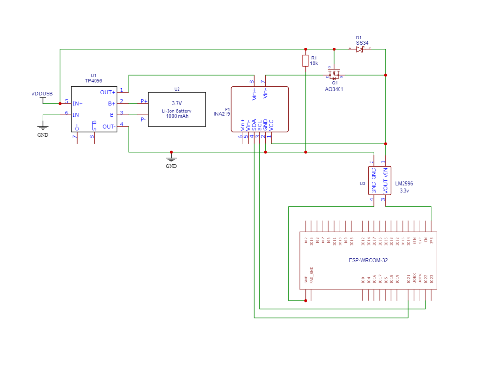
-
Things used in this project Hardware components Seeed Studio MR60BHA1 60GHz mmWave Module - Respiratory Heartbeat Detection × 1 DFRobot FireBeetle ESP32 IOT Microcontroller (Supports Wi-Fi & Bluetooth) × 1 DFRobot I2C 16x2 Arduino LCD Display Module × 1 Seeed Studio MLX90614 × 1 IR Sensor Module × 1 Linear Regulator (7805) × 2 Bridge Rectifier Diode, Miniature × 1 Capacitor 470 µF × 1 LED (generic) × 1 TaydaElectronics MINI RELAY SPDT 5 PINS 12VDC 10A 120V CONTACT × 1 9V 1A Switching Wall Power Supply × 1 Through Hole Resistor, 470 ohm × 1 Resistor 4.75k ohm × 1 DC Power Connector, Jack × 1 Buzzer × 1 Software apps and online services Arduino IDE Blynk Hand tools and fabrication machines Soldering iron (generic) Solder Wire, Lead Free Solder Flux, Soldering Story The MR60BHA1 60GHz mmWave Module is a versatile sensor that utilizes Frequency Modulation Continuous Wave (FMCW) detection to accurately measure breathing rate and heart rate, ensuring a completely private and secure environment, free from external interference. Equipped with a built-in standard algorithm and onboard antenna, the unit delivers simultaneous signal output with exceptional precision. It serves as an ideal solution for developing high-accuracy, self-regulating, privacy-protected, and secure biotic radar systems in consumer electronics, healthcare, and industrial applications. Block Diagram Beyond heart rate and respiration detection, the radar sensor can detect human presence in the operating area, enabling the creation of an automated device and appliance control system that conserves energy during unoccupied periods. Additionally, the system incorporates an IR temperature sensor to measure body temperature, allowing for illness and stress detection. Upon detecting significant vital variations, the buzzer activates as an alert. Simultaneously, all details are displayed on an LCD display and a mobile phone app via the ESP32 Wi-Fi module. The project involved various components, which can be identified in the Below provided image. Components Identification Get PCBs for Your Projects Manufactured This project was successfully completed because of the help and support from NextPCB. Guys if you have a PCB project, please visit their website and get exciting discounts and coupons. NextPCB offers high-quality, reliable PCB starting at $1.9, and multilayer starting at $6.9. Also, everyone can enjoy free PCB assembly for 5 boards! Also, NextPCB is having a year end sale in which anyone can register through their website and get a $30 Coupon which can be used for ordering PCBs. You can also try HQDFM free online PCB Gerber viewer to check your PCB design and avoid costly errors. Seeed Studio MR60BHA1 60GHz mmWave Module 1 / 2 The Seeed Studio MR60BHA1 60GHz mmWave Module is a versatile sensor module that utilizes Frequency Modulation Continuous Wave (FMCW) detection technology to accurately measure vital signs, including breathing rate and heart rate. It operates in a completely private and secure environment, free from external interference, making it an ideal solution for privacy-sensitive applications. Equipped with a built-in standard algorithm and onboard antenna, the unit delivers simultaneous signal output with exceptional precision. It serves as an ideal solution for developing high-accuracy, self-regulating, privacy-protected, and secure biotic radar systems in consumer electronics, healthcare, and industrial applications Key Features: Non-contact sensing for comfort and privacy High-accuracy, self-regulating, privacy-protected, and secure Low power consumption for extended battery life Compact size and lightweight for easy integration Applications: Consumer Electronics: Smart home automation, wearable devices, sleep monitoring Healthcare: Patient monitoring, vital signs detection, illness and stress detection Industrial Applications: Presence detection, safety monitoring, automation control Additional Features: IR temperature sensor to measure human temperature Buzzer to alert when vital variations are found LCD display and mobile phone app for data visualization Enhanced Health and Wellness Monitoring: The MR60BHA1 60GHz mmWave Module can be used to develop a comprehensive health and wellness monitoring system. By combining heart rate, respiration, and temperature measurements, the system can provide valuable insights into an individual's overall health and well-being. Automated Device and Appliance Control: The MR60BHA1 60GHz mmWave Module can also be used to create an automated device and appliance control system. By detecting the presence of a human in the operating area, the system can automatically turn on lights, adjust thermostats, and control other devices. Privacy-Protected and Secure: The MR60BHA1 60GHz mmWave Module operates in a completely private and secure environment, ensuring that personal health data is protected. The sensor does not require any physical contact with the user, and all data is processed locally on the device. Interfacing the MR60BHA1 60GHz mmWave Module with the ESP32 requires establishing a communication link between the two devices. This can be achieved using a Serial interface(Interface 1). For an implementation using the serial interface, refer to the following : Connect the MR60BHA1's TX pin to the ESP32's RXD (16)pin. Connect the MR60BHA1's RX pin to the ESP32's TXD(17) pin. Connect the MR60BHA1's GND pin to the ESP32's GND pin. Connect the MR60BHA1's 3.3V pin to the ESP32's 3.3V pin. Interface 2 is typically used for firmware upgrades on the MR60BHA1 60GHz mmWave Module. Interface 1 is typically used for data communication between the module and a host device. The following table summarizes the recommended use of each interface: However, there may be some cases where it is not recommended to use Interface 2 for firmware upgrades. For example, if the module is already running the latest firmware version, then there is no need to upgrade it. Additionally, if the module is experiencing instability or other problems, then it may be best to avoid upgrading the firmware until the problems have been resolved. In general, it is always a good idea to consult the user manual or other documentation for the MR60BHA1 60GHz mmWave Module before attempting to upgrade the firmware. This will help to ensure that the upgrade is performed safely and correctly. Please note that upgrading the firmware may void the warranty on the module. It is important to read and understand the warranty information before proceeding with any firmware upgrades. For More Technical details on MR60BHA1 60GHz mmWave Module follow the link https://wiki.seeedstudio.com/Radar_MR60BHA1/ Radar module operating range The radar module beam coverage is shown. The radar coverage is a three-dimensional sector of 80° horizontally and 80° tilted. Due to the radar beam characteristics, the radar has a relatively long range in the direction normal to the antenna face, but a shorter range if it deviates from the antenna normal. When the radar is mounted on top or at an angle, the radar beam range and the effective radiation space will reduce the radar range, which needs to be taken into account when using the radar. Installation method As the radar works mainly based on the respiratory heart rhythm causing undulating movements on the surface of the large muscles, the undulation of the human chest and back will be more pronounced, so this radar needs to be installed in the correct position to the human chest or back. Based on the radar mode of action, the following mounting options are considered for radar installation. (A) Overhead installation The radar beam is positioned vertically downwards towards the body, with the center of the radar beam corresponding to the position of the body's chest cavity. In this installation mode, a distance of ≤ 2 m is required between the radar and the body to be measured. (B) Tilt mounting With tilt mounting, the radar is fixed to a wall or bedside, the radar is mounted at an angle (as shown below) and the radar beam is directed at the body at an angle, with the center of the radar beam corresponding to the position of the human chest cavity. In this installation mode, the radial distance between the radar and the body to be measured is ≤ 2 m. (C) Horizontal installation The radar is placed horizontally (as shown in Fig Below), the radar is fixed to a wall, or placed on a table, the radar beam is directed toward the human body and the center of the radar beam corresponds to the position of the human thorax. The distance between the radar and the human body to be measured in this installation mode is ≤ 2 m. How the Project Works The project comprises an MR60BHA1 60GHz mmWave module for respiration, heart rate, and human presence detection, along with an MLX90614 sensor for contactless body temperature measurement. This project caters to two sectors: wellness monitoring and home or office automation. The ESP32 microcontroller serves as the project's central processing unit (CPU) and WiFi module. The MR60BHA1 sensor is connected using the ESP32's UART channels and the MLX90614 sensor is connected using ESP32's I2C Channels(SDA, SCL). To measure body temperature, the user needs to bring their hand near the sensor. A proximity sensor is deployed near the MLX90614 sensor to detect the presence of a hand and initialize the body temperature measurement. The measured temperature details will be displayed on the LCD panels and Blynk mobile application in Celsius units. To initiate heart rate and respiration rate measurement, the user must first deactivate the human presence detection switch. Once deactivated, the user should press the measurement button, and the ESP32 will initiate the measurement process by emitting a buzzer alert. The algorithms require a few seconds to collect and process the data, so please expect some minor delays before the accurate readings are displayed on the LCD screen and the Blynk mobile application. To activate the automation system based on human presence, the human presence detection switch must be activated. Once the switch is activated, the MR60BHA1 transitions into human presence detection mode. When human movements are detected within the radar's operating range, the ESP32 sends a pop-up notification to the Blynk app alerting the owner. Subsequently, an LED bulb will be turned on using a relay, demonstrating the MR60BHA1's capability in automating equipment. This human presence detection system also serves as a security product. The entire project is powered by a 12-volt DC power adapter. Considering the power requirements of the sensors, microcontroller, and other components, the voltage is regulated to 5 volts using a 7805 voltage regulator and to 3.3 volts using an AMS1117 voltage regulator. Project Code: #include "Arduino.h" #include <Wire.h> #include <LiquidCrystal_I2C.h> #include <Wire.h> #include <Adafruit_MLX90614.h> #include <WiFi.h> #include <WiFiClient.h> #include <BlynkSimpleEsp32.h> #define BLYNK_PRINT Serial #define BLYNK_TEMPLATE_ID "TMPL3gy4Fq2LC" #define BLYNK_TEMPLATE_NAME "Project" #define BLYNK_AUTH_TOKEN " char auth[] = "cxwnZjdeqqhWcGuObkEZ5OVt1WC_227g"; char ssid[] = "wifi"; char pass[] = "123456788"; Adafruit_MLX90614 mlx = Adafruit_MLX90614(); #define RXD2 16 #define TXD2 17 #include <60ghzbreathheart.h> LiquidCrystal_I2C lcd(0x27, 16, 2); BreathHeart_60GHz radar = BreathHeart_60GHz(&Serial2); unsigned long delay_Intial = 0; const long delay_interval = 1000; unsigned long measure_Intial = 0; const long measure_interval = 20000; int Human_pesence_pin = 27; int Human_presence; int Heart_rate_measure_button_pin = 26; int Heart_Button = 0; int IR_Sensor_pin = 33; int IR_Status; int relay = 32; int Buzzer = 25; void _delay() { delay_Intial = millis(); while((millis() - delay_Intial) <= delay_interval) { } } void Measure_Breath_Heart_rate() { radar.Breath_Heart(); //Breath and heartbeat information output if(radar.sensor_report != 0x00) { switch(radar.sensor_report) { case HEARTRATEVAL: Serial.print("Sensor monitored the current heart rate value is: "); Serial.print(radar.heart_rate, DEC); Serial.println(); lcd.clear(); lcd.setCursor(0,0); lcd.print("Heart Rate: "); lcd.print(radar.heart_rate); Blynk.virtualWrite(V0,radar.heart_rate); break; case BREATHVAL: Serial.print("Sensor monitored the current breath rate value is: "); Serial.print(radar.breath_rate, DEC); Serial.println(); lcd.setCursor(0,1); lcd.print("Breath_rate: "); lcd.print(radar.breath_rate, DEC); Blynk.virtualWrite(V1,radar.breath_rate); break; } } } void human_presence() { radar.HumanExis_Func(); //Human existence information output if(radar.sensor_report != 0x00){ switch(radar.sensor_report){ case BODYVAL: Serial.print("The parameters of human body signs are: "); Serial.println(radar.bodysign_val, DEC); Serial.println("----------------------------"); if(radar.bodysign_val >=15) { Blynk.virtualWrite(V3,20); measure_Intial = millis(); delay(1000); Blynk.virtualWrite(V3,0); while((millis() - measure_Intial) <= measure_interval) { digitalWrite(relay,HIGH); lcd.clear(); lcd.setCursor(0,0); lcd.print("Presence Found"); lcd.setCursor(0,1); lcd.print("Lights ON"); _delay(); } digitalWrite(relay,LOW); lcd.setCursor(0,1); lcd.print("Lights OFF"); _delay(); } break; } } } void HR_BR() { measure_Intial = millis(); while((millis() - measure_Intial) <= measure_interval) { Measure_Breath_Heart_rate(); } } void Measure_IR_Temperature() { Serial.print("*C\tObject = "); Serial.print(mlx.readObjectTempC()); Serial.println("*C"); lcd.clear(); lcd.setCursor(0,1); lcd.print("Body Temp: "); lcd.print(mlx.readObjectTempC()); Blynk.virtualWrite(V2,mlx.readObjectTempC()); _delay(); } void setup() { Serial.begin(115200);//RX0,TX0 OF ESP32 Serial2.begin(115200, SERIAL_8N1, RXD2, TXD2);//RX2,TX2 OF ESP32 pinMode(Heart_rate_measure_button_pin,INPUT); pinMode(IR_Sensor_pin,INPUT); pinMode(Human_pesence_pin,INPUT); pinMode(relay,OUTPUT); pinMode(Buzzer,OUTPUT); Wire.begin(); lcd.begin(); lcd.backlight(); mlx.begin(); radar.ModeSelect_fuc(1); Blynk.begin(auth, ssid, pass); } void loop() { Heart_Button = digitalRead(Heart_rate_measure_button_pin); IR_Status = digitalRead(IR_Sensor_pin); Human_presence = digitalRead(Human_pesence_pin); lcd.clear(); digitalWrite(relay,LOW); digitalWrite(Buzzer,LOW); Blynk.virtualWrite(V0,0); Blynk.virtualWrite(V1,0); Blynk.virtualWrite(V2,0); Blynk.virtualWrite(V3,0); switch(IR_Status) { case 1: Measure_IR_Temperature(); break; case 0: break; lcd.clear(); } switch(Heart_Button) { case 1: digitalWrite(Buzzer,HIGH); _delay(); digitalWrite(Buzzer,LOW); _delay(); Serial.println("Heart_rate_monitoring_system_acitve"); HR_BR(); break; } switch(Human_presence) { case 1: Serial.println("Human_presence_detection_active"); human_presence(); break; case 0: digitalWrite(relay,LOW); break; } Blynk.run(); }
-
Story A NeoPixel ring controlled by a DHT11 sensor and an Arduino Nano can be a fascinating project that combines temperature sensing with visual feedback. This article will guide you through the process of building such a system. Materials Needed Arduino Nano DHT11 Temperature and Humidity Sensor Neo Pixel Ring Jumper Wires Get PCBs For Your Projects Manufactured You must check out PCBWAY for ordering PCBs online for cheap! You get 10 good-quality PCBs manufactured and shipped to your doorstep for cheap. You will also get a discount on shipping on your first order. Upload your Gerber files onto PCBWAY to get them manufactured with good quality and quick turnaround time. PCBWay now could provide a complete product solution, from design to enclosure production. Check out their online Gerber viewer function. With reward points, you can get free stuff from their gift shop. Also, check out this useful blog on PCBWay Plugin for KiCad from here. Using this plugin, you can directly order PCBs in just one click after completing your design in KiCad. Step 1: Connecting the Hardware First, connect the DHT11 sensor and the Neo Pixel ring to the Arduino Nano. The DHT11 sensor can be connected to any digital pin on the Arduino Nano. The Neo Pixel ring should be connected to the D2 pin of the Arduino Nano. Step 2: Installing the Libraries You will need to install the DHT library and the Adafruit Neo Pixel library in your Arduino IDE. These libraries contain the necessary functions to interact with the DHT11 sensor and the Neo Pixel ring. First Navigate to Sketch > Include Library > Manage Libraries... In the Library Manager, there is a search box. Type “DHT sensor library” into the search box. In the search results, find the library named “DHT sensor library” by Adafruit. Click on it, then click the “Install” button. And that’s it! You’ve successfully installed the DHT11 sensor library in Arduino IDE. This library should now be available for inclusion in your sketches. Step 3: Programming the Arduino The next step is to program the Arduino Nano. The program should read the temperature from the DHT11 sensor and change the color of the Neo Pixel ring based on the temperature. For example, you could program the Neo Pixel ring to display a blue color when the temperature is below a certain threshold. A green color when the temperature is within a comfortable range, and a red color when the temperature is above a certain threshold. Step 4: Testing the System After programming the Arduino Nano, it’s time to test the system. Power up the Arduino and observe the color of the Neo Pixel ring. Try changing the temperature around the DHT11 sensor (for example, by blowing hot or cold air onto the sensor) and see if the color of the Neo Pixel ring changes accordingly. #include <Adafruit_NeoPixel.h> #include <Adafruit_Sensor.h> #include <DHT.h> #include <DHT_U.h> #define DHTTYPE DHT11 // DHT 11 #define DHTPIN 3 DHT_Unified dht(DHTPIN, DHTTYPE); #define PIN 2 // Neo Adafruit_NeoPixel strip = Adafruit_NeoPixel(8, PIN, NEO_GRB + NEO_KHZ800); void setup() { Serial.begin(115200); dht.begin(); sensor_t sensor; strip.begin(); strip.setBrightness(100); strip.show(); } void loop() { sensors_event_t event; dht.temperature().getEvent(&event); Serial.print(F("Temperature: ")); float temp1 = event.temperature; Serial.print(temp1); Serial.println(F("°C")); dht.humidity().getEvent(&event); Serial.print(F("Humidity: ")); float hum1 = event.relative_humidity; Serial.print(hum1); Serial.println(F("%")); if (temp1 >= 28 && temp1 < 31) { strip.clear(); // Set all pixel colors to 'off' for (int i = 0; i < 12; i++) { // For each pixel... strip.setPixelColor(i, strip.Color(0, 150, 0)); strip.show(); } } else if (temp1 < 28) { strip.clear(); for (int i = 0; i < 12; i++) { // For each pixel... strip.setPixelColor(i, strip.Color(0, 0, 150)); strip.show(); } } else { strip.clear(); for (int i = 0; i < 12; i++) { // For each pixel... strip.setPixelColor(i, strip.Color(150, 0, 0)); strip.show(); } } } Conclusion Building a DHT11-controlled Neo Pixel ring with an Arduino Nano is a fun and educational project combining temperature sensing and visual feedback. With this system, you can visually monitor the temperature in a room and get a sense of whether the temperature is within a comfortable range.
-
If you are looking for a way to add some colorful and dynamic lighting effects to your Arduino projects, you might want to try using neo-pixel rings. Neo-pixel rings are circular arrays of RGB LEDs that can be controlled individually by a single data line. They are easy to use and can create amazing patterns and animations with Arduino code. In this article, I will show you how to integrate a pixel ring with Arduino Nano, a small and cheap microcontroller board that can be programmed to interact with various sensors and devices. You will learn how to wire the neo-pixel ring to the Arduino Nano, how to install and use the Adafruit Neo Pixel library, and how to code some basic lighting effects using the neo-pixel ring. By the end of this article, you can create your custom lighting effects using a neo-pixel ring and Arduino Nano. You will also be able to modify and customize the code according to your preferences and needs. Let’s get started! Get PCBs For Your Projects Manufactured You must check out PCBWAY for ordering PCBs online for cheap! You get 10 good-quality PCBs manufactured and shipped to your doorstep for cheap. You will also get a discount on shipping on your first order. Upload your Gerber files onto PCBWAY to get them manufactured with good quality and quick turnaround time. PCBWay now could provide a complete product solution, from design to enclosure production. Check out their online Gerber viewer function. With reward points, you can get free stuff from their gift shop. Also, check out this useful blog on PCBWay Plugin for KiCad from here. Using this plugin, you can directly order PCBs in just one click after completing your design in KiCad. Materials and tools: 8-bit neo-pixel ring Arduino nano Jumper wires Mini USB cable Adafruit Neo Pixel library for Arduino Wiring: Connect the IN pin of the neo-pixel ring to the D2 pin of the Arduino nano Connect the VCC pin of the neo-pixel ring to the +5V pin of the Arduino nano Connect the GND pin of the neo-pixel ring to the GND pin of the Arduino nano Programming: Once all the connections are made, open up the Arduino IDE and go to the Include library option. Then add the downloaded zip library that we have previously mentioned. Once the library installation is successful, you can see the neo pixel library examples in the examples sketch. Next, open up the strandtest_wheel sketch and change the pin to 2. Because we have connected our Neo pixel to the D2 pin of the Arduino. # include <Adafruit_NeoPixel.h> #ifdef __AVR__ #include <avr/power.h> #endif #define PIN 2 // Parameter 1 = number of pixels in strip // Parameter 2 = Arduino pin number (most are valid) // Parameter 3 = pixel type flags, add together as needed: // NEO_KHZ800 800 KHz bitstream (most NeoPixel products w/WS2812 LEDs) // NEO_KHZ400 400 KHz (classic 'v1' (not v2) FLORA pixels, WS2811 drivers) // NEO_GRB Pixels are wired for GRB bitstream (most NeoPixel products) // NEO_RGB Pixels are wired for RGB bitstream (v1 FLORA pixels, not v2) // NEO_RGBW Pixels are wired for RGBW bitstream (NeoPixel RGBW products) Adafruit_NeoPixel strip = Adafruit_NeoPixel(8, PIN, NEO_GRB + NEO_KHZ800); // IMPORTANT: To reduce NeoPixel burnout risk, add 1000 uF capacitor across // pixel power leads, add 300 - 500 Ohm resistor on first pixel's data input // and minimize distance between Arduino and first pixel. Avoid connecting // on a live circuit...if you must, connect GND first. void setup() { // This is for Trinket 5V 16MHz, you can remove these three lines if you are not using a Trinket #if defined (__AVR_ATtiny85__) if (F_CPU == 16000000) clock_prescale_set(clock_div_1); #endif // End of trinket special code strip.begin(); strip.setBrightness(100); strip.show(); // Initialize all pixels to 'off' } void loop() { // Some example procedures showing how to display to the pixels: colorWipe(strip.Color(255, 0, 0), 50); // Red colorWipe(strip.Color(0, 255, 0), 50); // Green colorWipe(strip.Color(0, 0, 255), 50); // Blue //colorWipe(strip.Color(0, 0, 0, 255), 50); // White RGBW // Send a theater pixel chase in... theaterChase(strip.Color(127, 127, 127), 50); // White theaterChase(strip.Color(127, 0, 0), 50); // Red theaterChase(strip.Color(0, 0, 127), 50); // Blue rainbow(20); rainbowCycle(20); theaterChaseRainbow(50); } // Fill the dots one after the other with a color void colorWipe(uint32_t c, uint8_t wait) { for(uint16_t i=0; i<strip.numPixels(); i++) { strip.setPixelColor(i, c); strip.show(); delay(wait); } } void rainbow(uint8_t wait) { uint16_t i, j; for(j=0; j<256; j++) { for(i=0; i<strip.numPixels(); i++) { strip.setPixelColor(i, Wheel((i+j) & 255)); } strip.show(); delay(wait); } } // Slightly different, this makes the rainbow equally distributed throughout void rainbowCycle(uint8_t wait) { uint16_t i, j; for(j=0; j<256*5; j++) { // 5 cycles of all colors on wheel for(i=0; i< strip.numPixels(); i++) { strip.setPixelColor(i, Wheel(((i * 256 / strip.numPixels()) + j) & 255)); } strip.show(); delay(wait); } } //Theatre-style crawling lights. void theaterChase(uint32_t c, uint8_t wait) { for (int j=0; j<10; j++) { //do 10 cycles of chasing for (int q=0; q < 3; q++) { for (uint16_t i=0; i < strip.numPixels(); i=i+3) { strip.setPixelColor(i+q, c); //turn every third pixel on } strip.show(); delay(wait); for (uint16_t i=0; i < strip.numPixels(); i=i+3) { strip.setPixelColor(i+q, 0); //turn every third pixel off } } } } //Theatre-style crawling lights with rainbow effect void theaterChaseRainbow(uint8_t wait) { for (int j=0; j < 256; j++) { // cycle all 256 colors in the wheel for (int q=0; q < 3; q++) { for (uint16_t i=0; i < strip.numPixels(); i=i+3) { strip.setPixelColor(i+q, Wheel( (i+j) % 255)); //turn every third pixel on } strip.show(); delay(wait); for (uint16_t i=0; i < strip.numPixels(); i=i+3) { strip.setPixelColor(i+q, 0); //turn every third pixel off } } } } // Input a value 0 to 255 to get a color value. // The colours are a transition r - g - b - back to r. uint32_t Wheel(byte WheelPos) { WheelPos = 255 - WheelPos; if(WheelPos < 85) { return strip.Color(255 - WheelPos * 3, 0, WheelPos * 3); } if(WheelPos < 170) { WheelPos -= 85; return strip.Color(0, WheelPos * 3, 255 - WheelPos * 3); } WheelPos -= 170; return strip.Color(WheelPos * 3, 255 - WheelPos * 3, 0); } Next, select the correct port and board. Here is the response. Conclusion: You have learned how to connect neo pixel ring with Arduino Nano and create some lighting effects using Arduino code, You can try different colors, patterns, and speeds for your animations by changing the code parameters. You can also use other types of neo-pixel products, such as strips, matrices, or jewels, for more variety and complexity.
-
Sending data from an Arduino microcontroller to the ThingSpeak platform using a GPRS module is not a novel project concept. While it may appear outdated in numerous regions, owing to the rapid evolution of communication technologies such as 2G, 3G, 4G, 5G, and the potential for 6G, this is not the case in my country. In India, 2G technologies remain prevalent, and major network operators have confirmed their intent to sustain 2G services. The legacy project documents that were originally designed with the SIM800 module may necessitate slight adjustments. This project will prove invaluable to those who continue to rely on 2G and GPRS technology. It offers essential support and guidance for individuals who intend to persist with these communication methods. Sending data from an Arduino microcontroller to the ThingSpeak platform using a GPRS module, specifically the SIM800, is a fundamental concept. The crucial aspect is that this communication method operates independently of Wi-Fi, constituting an IoT connectivity solution that relies on GPRS for data transmission. 1 / 2 In this project, LM35 temperature sensor data is being transmitted to the ThingSpeak platform through an Arduino Nano and a SIM800 module. The SIM800 module is leveraged to establish a GPRS connection, facilitating the transmission of data to ThingSpeak at specified intervals. To ensure a reliable connection between ThingSpeak and the hardware, users must configure the SIM800 module to establish a connection with their mobile network. This configuration encompasses setting the Access Point Name (APN) specific to their mobile carrier. It's important to note that the specific AT commands for this configuration may vary based on the user's chosen mobile network provider. For this project, I utilized the services of the network provider Airtel to establish the connection. Communication between the hardware components, specifically the SIM800 module, Arduino Nano, and ThingSpeak platform, relies entirely on AT commands. To ensure successful project implementation and effectively troubleshoot any issues that may arise, users must possess a basic understanding of SIM800 AT commands. This knowledge is crucial for configuring, managing, and diagnosing the communication process and resolving potential challenges during the project. Get PCBs For Your Projects Manufactured You must check out PCBWAY for ordering PCBs online for cheap! You get 10 good-quality PCBs manufactured and shipped to your doorstep for cheap. You will also get a discount on shipping on your first order. Upload your Gerber files onto PCBWAY to get them manufactured with good quality and quick turnaround time. PCBWay now could provide a complete product solution, from design to enclosure production. Check out their online Gerber viewer function. With reward points, you can get free stuff from their gift shop. Also, check out this useful blog on PCBWay Plugin for KiCad from here. Using this plugin, you can directly order PCBs in just one click after completing your design in KiCad. Networking testing The table provided below lists several common AT commands that serve to swiftly and effectively verify the proper functioning of the SIM800C's AT serial communication and network connection. Before proceeding with the steps outlined for the network communication demonstration, it is advisable to conduct a straightforward network test. This preliminary test ensures that the intended network connection is in working order and fully operational. TCP/IP Communication The SIM800 serial module's TCP/IP application offers two connection modes, selectable through the AT command `AT CIPMUX=<n>`. When `AT CIPMUX` is set to 0 (`AT+CIPMUX=0`), it operates in single-link mode. When `AT CIPMUX` is set to 1 (`AT+CIPMUX=1`), it operates in multi-link mode. By default, the module is configured in single-link mode. In single-link mode, the SIM800 serial module can function in both transparent and non-transparent transmission modes. In both of these modes, the module can be configured as either a TCP/UDP client or a TCP server. In multi-link mode, the SIM800 serial module operates solely in non-transparent mode. In this mode, it can serve as a TCP/UDP client, allowing for the establishment of a maximum of 6 connections. It can also be configured as a TCP server, with support for 5 TCP/UDP clients. SIM800C TCP/IP operates with a multi-client architecture by default, enabling up to five sockets for TCP or UDP connections. In the upcoming demonstrations, our focus will be on the client communication capabilities of the SIM800C module. Specifically, we will explore its operation in single-link non-transparent mode and transparent mode. Client communication in non-transparent mode Client communication in non-transparent mode refers to the way the SIM800C module interacts with remote servers or devices when it acts as a client, transmitting data using a specific protocol such as TCP or UDP. In non-transparent mode, the module sends and receives data through AT commands and does not directly pass data between the microcontroller and the remote server. This mode provides control over the data transmission process, allowing you to send and receive data, manage connections, and configure communication settings using AT commands. It is suitable for applications where you need fine-grained control over the communication process and want to ensure data integrity. To use the SIM800C in client communication in non-transparent mode, you will typically configure the module using appropriate AT commands and establish connections with remote servers or devices for data exchange. Client communication in transparent transmission mode Client communication in transparent transmission mode refers to the SIM800C module's ability to act as a client while allowing data to flow directly between the microcontroller (e.g., an Arduino) and a remote server or device. In this mode, the SIM800C module operates as a transparent bridge, forwarding data between the microcontroller and the remote server without the need for explicit AT commands to send or receive each piece of data. This mode simplifies data transfer by treating the SIM800C module as a transparent conduit. Data sent by the microcontroller is transmitted to the remote server without manual packetization, and data received from the server is forwarded to the microcontroller without manual processing. Using the SIM800C in transparent transmission mode is advantageous when you want to streamline data transfer and reduce the complexity of managing data packets and AT commands for each communication task. It's particularly useful for applications where data throughput and efficiency are essential. HTTP Communication This chapter provides an overview of the HTTP communication capabilities of the SIM800C module, focusing on HTTP GET and HTTP POST methods. For in-depth information about HTTP and FTP (File Transfer Protocol) communication with the SIM800C module, please refer to the "SIM800C Series_IP_Application_Note." This additional resource will provide comprehensive details and guidelines for utilizing these communication functions effectively. HTTP GET HTTP Post SIM800 Series_AT Command Manual_V1.10 SIM800 Series_TCPIP_Application Note_V1.02 Connection Diagram Establishing Communication Between Arduino Nano, SIM800, and ThingSpeak (Serial Monitor Data Captured During Project Execution). AT+CSTT="airtelgprs.com"<CR> OK AT+CIICR<CR> OK AT+CIFSR<CR> 100.78.215.26 AT+CIPSPRT=0<CR> OK AT+CIPSTART="TCP","api.thingspeak.com","80"<CR> OK CONNECT OK<CR>AT+CIPSEND<CR>GET https://api.thingspeak.com/update?api_key=5XC1TCVONJVK1PNN&field1=20.00&field2=10.00 GET https://api.thingspeak.com/update?api_key=5XC1TCVONJVK1PNN&<SUB> SEND OK 6 CLOSED <CR>AT+CIPSHUT<CR>Temperature = 20.00 °C Humidity = 10.00 % SHUT OK AT<CR> OK AT+CPIN?<CR> +CPIN: READY OK AT+CREG?<CR> +CAT+CSTT="airtelgprs.com"<CR> OK AT+CIICR<CR> OK AT+CIFSR<CR> 100.90.199.122 AT+CIPSPRT=0<CR> OK AT+CIPSTART="TCP","api.thingspeak.com","80"<CR> OK CONNECT OK<CR>AT+CIPSEND<CR>GET https://api.thingspeak.com/update?api_key=5XC1TCVONJVK1PNN&field1=20.00&field2=10.00 GET https://api.thingspeak.com/update?api_key=5XC1TCVONJVK1PNN&<SUB> SEND OK 7 CLOSED <CR>AT+CIPSHUT<CR>Temperature = 20.00 °C Humidity = 10.00 % SHUT OK AT<CR> OK AT+CPIN?<CR> +CPIN: READY OK AT+CREG?<CR> +CAT+CSTT="airtelgprs.com"<CR> OK AT+CIICR<CR> OK AT+CIFSR<CR> 100.102.108.63 AT+CIPSPRT=0<CR> OK AT+CIPSTART="TCP","api.thingspeak.com","80"<CR> OK CONNECT OK<CR>AT+CIPSEND<CR>GET https://api.thingspeak.com/update?api_key=5XC1TCVONJVK1PNN&field1=20.00&field2=10.00 GET https://api.thingspeak.com/update?api_key=5XC1TCVONJVK1PNN&<SUB> SEND OK 8 CLOSED
-
Telegram is a popular messaging app that offers end-to-end encryption, cloud-based storage, and a variety of features for communication. One of these features is the ability to create and interact with bots, which are automated programs that can perform tasks or provide information. In this blog post, I will show you how to use Telegram bots to control your home automation system with Node-RED, a visual programming tool that allows you to connect and orchestrate devices, services, and APIs. Get PCBs For Your Projects Manufactured You must check out PCBWAY for ordering PCBs online for cheap! You get 10 good-quality PCBs manufactured and shipped to your doorstep for cheap. You will also get a discount on shipping on your first order. Upload your Gerber files onto PCBWAY to get them manufactured with good quality and quick turnaround time. PCBWay now could provide a complete product solution, from design to enclosure production. Check out their online Gerber viewer function. With reward points, you can get free stuff from their gift shop. Also, check out this useful blog on PCBWay Plugin for KiCad from here. Using this plugin, you can directly order PCBs in just one click after completing your design in KiCad. 1. What You Need: To follow this tutorial, you will need: A Telegram account and a smartphone with the Telegram app installed. A Node-RED instance running on a device that can access your home automation system. You can use a Raspberry Pi, a computer, or a cloud service. For more information on how to install and run Node-RED, see here. The node-red-contrib-telegrambot node provides Telegram bot nodes for Node-RED. You can install it from the Node-RED palette manager or by running the following command in your Node-RED directory: npm install node-red-contrib-telegrambot A Telegram bot token is a unique identifier for your bot. You can create a bot and get its token by talking to the @BotFather bot on Telegram. For more details. A chat ID is a unique identifier for the chat between you and your bot. You can get your chat ID by sending a message to your bot. 2. How It Works: The basic idea is to use Node-RED to create a flow that receives messages from your Telegram bot, parses them to extract commands or queries, and then sends commands or responses back to your bot. The node-red-contrib-telegrambot node provides two main nodes for this purpose: the receiver node and the sender node. The receiver node listens for messages from your bot and outputs a message object with the following properties: msg.payload.chatId: The chat ID of the sender. msg.payload.type: The type of the message, such as “message”, “photo”, “location”, etc. msg.payload.content: The content of the message, such as a text string, a file ID, or an object with additional data. The sender node takes a message object as input and sends it to your bot. The message object should have the following properties: msg.payload.chatId: The chat ID of the recipient. msg.payload.type: The type of the message, such as “message”, “photo”, “location”, etc. msg.payload.content: The content of the message, such as a text string, a file ID, or an object with additional data. You can use other nodes in between the receiver and sender nodes to process the messages and perform actions on your home automation system. For example, you can use a switch node to route messages based on their type or content, a function node to write custom logic in JavaScript, or an HTTP request node to call external APIs. 3. A little recap of the previous blog: In the previous blog, we have seen how to use the telegram bot with node-red to trigger the temperature data. In this blog, we are going to see how to automate and trigger the Telegram bot to control the GPIO. 4. Telegram to Node-Red: In the last article, we have seen how to trigger the sensor readings from Node-Red to Telegram, now let's see how to trigger and get the sensor data from Telegram Bot. First, we need to use the telegram receiver node. And configure the node with your bot credentials. Then add a debug block. Next, just try to send some messages to your bot and look at the response in the debug console. Now, you can see your texts are coming under payload.content. So, we are going to filter the content then based on the content we are going to trigger the actions. Here are my complete blocks. In this, I have tried to filter the contents as Green, Red, Blue, Off, and Env. Based on the contents we are going to trigger the neo pixels with certain colors. Finally, just deploy the flow, open the telegram bot, and test out the connections. Let's try out the neo pixels. [ { "id": "eb8f9c0d054be30c", "type": "tab", "label": "Flow 2", "disabled": false, "info": "", "env": [] }, { "id": "ea63aa67.c972f", "type": "template", "z": "eb8f9c0d054be30c", "name": "", "field": "payload", "fieldType": "msg", "format": "handlebars", "syntax": "mustache", "template": "{\"chatId\": 5379039379,\n\"type\":\"message\",\n\"content\":\"Temperature : {{payload}}, Humidity : {{humidity}}\"}", "output": "json", "x": 660, "y": 360, "wires": [ [ "9e00d0a7.d5ccf", "600063bd96d765e6" ] ] }, { "id": "9e00d0a7.d5ccf", "type": "debug", "z": "eb8f9c0d054be30c", "name": "", "active": true, "tosidebar": true, "console": false, "tostatus": false, "complete": "payload", "targetType": "msg", "statusVal": "", "statusType": "auto", "x": 830, "y": 300, "wires": [] }, { "id": "600063bd96d765e6", "type": "telegram sender", "z": "eb8f9c0d054be30c", "name": "roboerto_bot", "bot": "ae1a60539b8e5308", "haserroroutput": true, "outputs": 2, "x": 830, "y": 380, "wires": [ [], [] ] }, { "id": "f2f9819ae972ae60", "type": "rpi-dht22", "z": "eb8f9c0d054be30c", "name": "", "topic": "rpi-dht22", "dht": "11", "pintype": 1, "pin": "7", "x": 500, "y": 380, "wires": [ [ "ea63aa67.c972f" ] ] }, { "id": "e4b8f2dd860a7973", "type": "telegram receiver", "z": "eb8f9c0d054be30c", "name": "", "bot": "ae1a60539b8e5308", "saveDataDir": "", "filterCommands": false, "x": 290, "y": 200, "wires": [ [ "ea58984a24ea493e" ], [] ] }, { "id": "ea58984a24ea493e", "type": "switch", "z": "eb8f9c0d054be30c", "name": "", "property": "payload.content", "propertyType": "msg", "rules": [ { "t": "eq", "v": "Green", "vt": "str" }, { "t": "eq", "v": "Red", "vt": "str" }, { "t": "eq", "v": "Off", "vt": "str" }, { "t": "eq", "v": "Blue", "vt": "str" }, { "t": "eq", "v": "Env", "vt": "str" }, { "t": "eq", "v": "Rainbow", "vt": "str" } ], "checkall": "true", "repair": false, "outputs": 6, "x": 450, "y": 140, "wires": [ [ "b410ed94340bb528" ], [ "13aa73e421c429c7" ], [ "4ed36e19be451327" ], [ "db816a1f10392614" ], [ "f2f9819ae972ae60" ], [] ] }, { "id": "b0edb6e1c2807920", "type": "rpi-neopixels", "z": "eb8f9c0d054be30c", "name": "Neo Pixel", "gpio": "18", "pixels": "8", "bgnd": "", "fgnd": "", "wipe": "60", "mode": "pixels", "rgb": "rgb", "brightness": "100", "gamma": true, "x": 660, "y": 100, "wires": [] }, { "id": "13aa73e421c429c7", "type": "function", "z": "eb8f9c0d054be30c", "name": "Red Led", "func": "\nmsg.payload = \"255,0,0\"\nreturn msg;\n\n\n", "outputs": 1, "timeout": "", "noerr": 0, "initialize": "", "finalize": "", "libs": [], "x": 660, "y": 200, "wires": [ [ "b0edb6e1c2807920", "0d73aa1efdf96848" ] ] }, { "id": "b410ed94340bb528", "type": "function", "z": "eb8f9c0d054be30c", "name": "Green Led", "func": "\nmsg.payload = \"0,255,0\"\nreturn msg;\n\n\n", "outputs": 1, "timeout": "", "noerr": 0, "initialize": "", "finalize": "", "libs": [], "x": 670, "y": 160, "wires": [ [ "b0edb6e1c2807920", "c173db3cc3868fe8" ] ] }, { "id": "4ed36e19be451327", "type": "function", "z": "eb8f9c0d054be30c", "name": "Off", "func": "\nmsg.payload = \"0,0,0\"\nreturn msg;\n\n\n", "outputs": 1, "timeout": "", "noerr": 0, "initialize": "", "finalize": "", "libs": [], "x": 650, "y": 240, "wires": [ [ "b0edb6e1c2807920", "02e43d4dd4523371" ] ] }, { "id": "db816a1f10392614", "type": "function", "z": "eb8f9c0d054be30c", "name": "Blue Led", "func": "\nmsg.payload = \"0,0,255\"\nreturn msg;\n\n\n", "outputs": 1, "timeout": "", "noerr": 0, "initialize": "", "finalize": "", "libs": [], "x": 660, "y": 280, "wires": [ [ "b0edb6e1c2807920", "15dcd2ff9b951c47" ] ] }, { "id": "c173db3cc3868fe8", "type": "template", "z": "eb8f9c0d054be30c", "name": "", "field": "payload", "fieldType": "msg", "format": "handlebars", "syntax": "mustache", "template": "{\"chatId\": 5379039379,\n\"type\":\"message\",\n\"content\":\"Green LED Triggered\"}", "output": "json", "x": 860, "y": 80, "wires": [ [ "62f3360544d9ca11", "4abe16519bcdcaca" ] ] }, { "id": "62f3360544d9ca11", "type": "debug", "z": "eb8f9c0d054be30c", "name": "", "active": true, "tosidebar": true, "console": false, "tostatus": false, "complete": "payload", "targetType": "msg", "statusVal": "", "statusType": "auto", "x": 1030, "y": 80, "wires": [] }, { "id": "4abe16519bcdcaca", "type": "telegram sender", "z": "eb8f9c0d054be30c", "name": "roboerto_bot", "bot": "ae1a60539b8e5308", "haserroroutput": true, "outputs": 2, "x": 1030, "y": 120, "wires": [ [], [] ] }, { "id": "0d73aa1efdf96848", "type": "template", "z": "eb8f9c0d054be30c", "name": "", "field": "payload", "fieldType": "msg", "format": "handlebars", "syntax": "mustache", "template": "{\"chatId\": 5379039379,\n\"type\":\"message\",\n\"content\":\"Red LED Triggered\"}", "output": "json", "x": 860, "y": 120, "wires": [ [ "4795fb81ce5c47a6", "12c1a78b02583d94" ] ] }, { "id": "4795fb81ce5c47a6", "type": "debug", "z": "eb8f9c0d054be30c", "name": "", "active": true, "tosidebar": true, "console": false, "tostatus": false, "complete": "payload", "targetType": "msg", "statusVal": "", "statusType": "auto", "x": 1030, "y": 180, "wires": [] }, { "id": "12c1a78b02583d94", "type": "telegram sender", "z": "eb8f9c0d054be30c", "name": "roboerto_bot", "bot": "ae1a60539b8e5308", "haserroroutput": true, "outputs": 2, "x": 1030, "y": 220, "wires": [ [], [] ] }, { "id": "15dcd2ff9b951c47", "type": "template", "z": "eb8f9c0d054be30c", "name": "", "field": "payload", "fieldType": "msg", "format": "handlebars", "syntax": "mustache", "template": "{\"chatId\": 5379039379,\n\"type\":\"message\",\n\"content\":\"Blue LED Triggered\"}", "output": "json", "x": 860, "y": 160, "wires": [ [ "751fda5416547778", "46ea1f39f11d1b65" ] ] }, { "id": "751fda5416547778", "type": "debug", "z": "eb8f9c0d054be30c", "name": "", "active": true, "tosidebar": true, "console": false, "tostatus": false, "complete": "payload", "targetType": "msg", "statusVal": "", "statusType": "auto", "x": 1030, "y": 280, "wires": [] }, { "id": "46ea1f39f11d1b65", "type": "telegram sender", "z": "eb8f9c0d054be30c", "name": "roboerto_bot", "bot": "ae1a60539b8e5308", "haserroroutput": true, "outputs": 2, "x": 1030, "y": 320, "wires": [ [], [] ] }, { "id": "02e43d4dd4523371", "type": "template", "z": "eb8f9c0d054be30c", "name": "", "field": "payload", "fieldType": "msg", "format": "handlebars", "syntax": "mustache", "template": "{\"chatId\": 5379039379,\n\"type\":\"message\",\n\"content\":\"LED Off\"}", "output": "json", "x": 860, "y": 220, "wires": [ [ "e9aaa495e9c42799", "0730f1a37c585783" ] ] }, { "id": "e9aaa495e9c42799", "type": "debug", "z": "eb8f9c0d054be30c", "name": "", "active": true, "tosidebar": true, "console": false, "tostatus": false, "complete": "payload", "targetType": "msg", "statusVal": "", "statusType": "auto", "x": 1030, "y": 380, "wires": [] }, { "id": "0730f1a37c585783", "type": "telegram sender", "z": "eb8f9c0d054be30c", "name": "roboerto_bot", "bot": "ae1a60539b8e5308", "haserroroutput": true, "outputs": 2, "x": 1030, "y": 420, "wires": [ [], [] ] }, { "id": "e30abb1d7e9afcb0", "type": "inject", "z": "eb8f9c0d054be30c", "name": "Green", "props": [ { "p": "payload" }, { "p": "topic", "vt": "str" } ], "repeat": "", "crontab": "", "once": false, "onceDelay": 0.1, "topic": "", "payload": "", "payloadType": "date", "x": 290, "y": 280, "wires": [ [ "b410ed94340bb528" ] ] }, { "id": "4a2a01d9556ad50f", "type": "inject", "z": "eb8f9c0d054be30c", "name": "Blue", "props": [ { "p": "payload" }, { "p": "topic", "vt": "str" } ], "repeat": "", "crontab": "", "once": false, "onceDelay": 0.1, "topic": "", "payload": "", "payloadType": "date", "x": 290, "y": 360, "wires": [ [ "db816a1f10392614" ] ] }, { "id": "3f3ce5ea96251201", "type": "inject", "z": "eb8f9c0d054be30c", "name": "Red", "props": [ { "p": "payload" }, { "p": "topic", "vt": "str" } ], "repeat": "", "crontab": "", "once": false, "onceDelay": 0.1, "topic": "", "payload": "", "payloadType": "date", "x": 290, "y": 320, "wires": [ [ "13aa73e421c429c7" ] ] }, { "id": "3f2c1cebdde09f03", "type": "inject", "z": "eb8f9c0d054be30c", "name": "Off", "props": [ { "p": "payload" }, { "p": "topic", "vt": "str" } ], "repeat": "", "crontab": "", "once": false, "onceDelay": 0.1, "topic": "", "payload": "", "payloadType": "date", "x": 290, "y": 400, "wires": [ [ "4ed36e19be451327" ] ] }, { "id": "26b87a7af5f875cc", "type": "inject", "z": "eb8f9c0d054be30c", "name": "Env", "props": [ { "p": "payload" }, { "p": "topic", "vt": "str" } ], "repeat": "", "crontab": "", "once": false, "onceDelay": 0.1, "topic": "", "payload": "", "payloadType": "date", "x": 290, "y": 440, "wires": [ [ "f2f9819ae972ae60" ] ] }, { "id": "ae1a60539b8e5308", "type": "telegram bot", "botname": "roboerto_bot", "usernames": "", "chatids": "", "baseapiurl": "", "updatemode": "polling", "pollinterval": "300", "usesocks": false, "sockshost": "", "socksprotocol": "socks5", "socksport": "6667", "socksusername": "anonymous", "sockspassword": "", "bothost": "", "botpath": "", "localbotport": "8443", "publicbotport": "8443", "privatekey": "", "certificate": "", "useselfsignedcertificate": false, "sslterminated": false, "verboselogging": false } ] 5. Conclusion: In this blog post, I showed you how to use Telegram bots to control your home automation system with Node-RED. You can use this method to create your own custom interface for your smart home devices and services. You can also extend the functionality of your bot by adding more nodes and logic to your flow. For example, you can use the command node to create custom commands with parameters, the callback query node to handle inline buttons, or the answer inline query node to provide suggestions. You can also use other nodes from the node-red-contrib-telegrambot package or other Node-RED packages to integrate with more Telegram features or other platforms. I hope you enjoyed this tutorial and learned something new. If you have any questions or feedback, please leave a comment below. Happy coding!
-
The project titled "Ethernet-Enhanced LoRa Gateway: Minimizing Delay, Maximizing Security" focuses on the development of a LoRa (Long Range) gateway with Ethernet connectivity. This gateway serves as a critical link between IoT devices and the internet, providing two key advantages: Low Latency: By utilizing Ethernet, the gateway minimizes data transmission delay, ensuring that IoT data is transmitted quickly and efficiently. This is crucial for real-time or time-sensitive applications. Enhanced Security: The project emphasizes robust security measures to protect IoT data. Ethernet connections can be secured with standard network security protocols, ensuring the integrity and confidentiality of transmitted data. In summary, this project aims to create a high-performance LoRa gateway that optimizes data transfer speed and prioritizes data security, making it ideal for a wide range of IoT applications where low latency and data protection are paramount. In this project, I am creating a LoRa Gateway using Ethernet. The project consists of a LoRa Transmitter and LoRa gateway section. Get PCBs For Your Projects Manufactured You must check out PCBWAY for ordering PCBs online for cheap! You get 10 good-quality PCBs manufactured and shipped to your doorstep for cheap. You will also get a discount on shipping on your first order. Upload your Gerber files onto PCBWAY to get them manufactured with good quality and quick turnaround time. PCBWay now could provide a complete product solution, from design to enclosure production. Check out their online Gerber viewer function. With reward points, you can get free stuff from their gift shop. Also, check out this useful blog on PCBWay Plugin for KiCad from here. Using this plugin, you can directly order PCBs in just one click after completing your design in KiCad. LoRa Transmitter In the transmitter part of the system the following blocks are utilized : Sensor Array: The transmitter is equipped with various sensors, including a temperature sensor(SI7051) for environmental data and accelerometers and gyroscopes(MPU6050) for motion sensing. These sensors continuously collect data. Microcontroller: The microcontroller (XIAO SAMD21)processes the sensor data, monitoring both temperature variations and changes in the device's orientation or position. LoRa Transmitter: Upon detecting a significant change in position, the microcontroller triggers the LoRa transmitter (WIO E5)to send an alert message. This message includes the altered position information and the concurrently recorded temperature data. Power Source: The transmitter operates on a power-efficient setup, utilizing two AA-size batteries that provide power for an extended period, typically lasting several months. The primary purpose of this transmitter is to collect sensor data, detect substantial changes in position, and efficiently transmit alert messages containing both positional and temperature information via LoRa technology. This design ensures long-lasting operation without frequent battery replacements, making it suitable for remote or unattended applications. Block Diagram Of Transmitter Connection Diagram Of The Transmitter Transmitter Part Code #include <Arduino.h> #include <Wire.h> #include "ClosedCube_Si7051.h" #include "MPU6050.h" ClosedCube_Si7051 si7051; MPU6050 accelgyro; #if I2CDEV_IMPLEMENTATION == I2CDEV_ARDUINO_WIRE #include "Wire.h" #endif int data1=0; int data2=0; int data3=0; int data4=0; int16_t ax, ay, az; int16_t gx, gy, gz; #define OUTPUT_READABLE_ACCELGYRO static char recv_buf[512]; static bool is_exist = false; int a_x,a_y,a_z; static int at_send_check_response(char *p_ack, int timeout_ms, char *p_cmd, ...) { int ch = 0; int index = 0; int startMillis = 0; va_list args; memset(recv_buf, 0, sizeof(recv_buf)); va_start(args, p_cmd); Serial1.printf(p_cmd, args); Serial.printf(p_cmd, args); va_end(args); delay(200); startMillis = millis(); if (p_ack == NULL) { return 0; } do { while (Serial1.available() > 0) { ch = Serial1.read(); recv_buf[index++] = ch; Serial.print((char)ch); delay(2); } if (strstr(recv_buf, p_ack) != NULL) { return 1; } } while (millis() - startMillis < timeout_ms); return 0; } static int node_send(uint32_t timeout) { static uint16_t count = 0; int ret = 0; char data[32]; char cmd[128]; memset(data, 0, sizeof(data)); sprintf(data, "%04X,%04X,%04X,%04X", data1, data2, data3,data4); sprintf(cmd, "AT+TEST=TXLRPKT,\"5345454544%s\"\r\n", data); ret = at_send_check_response("TX DONE", 2000, cmd); if (ret == 1) { Serial.print("Sent successfully!\r\n"); } else { Serial.print("Send failed!\r\n"); } data1 = si7051.readTemperature(); data2 = a_z; return ret; } void setup(void) { Serial.begin(115200); si7051.begin(0x40); // default I2C address is 0x40 and 14-bit measurement resolution Serial1.begin(9600); #if I2CDEV_IMPLEMENTATION == I2CDEV_ARDUINO_WIRE Wire.begin(); #elif I2CDEV_IMPLEMENTATION == I2CDEV_BUILTIN_FASTWIRE Fastwire::setup(400, true); #endif accelgyro.initialize(); uint16_t error; char errorMessage[256]; if (at_send_check_response("+AT: OK", 100, "AT\r\n")) { is_exist = true; at_send_check_response("+MODE: TEST", 1000, "AT+MODE=TEST\r\n"); at_send_check_response("+TEST: RFCFG", 1000, "AT+TEST=RFCFG,866,SF12,125,12,15,14,ON,OFF,OFF\r\n"); delay(200); } else { is_exist = false; Serial.print("No E5 module found.\r\n"); } } void loop(void) { accelgyro.getMotion6(&ax, &ay, &az, &gx, &gy, &gz); Serial.print("Sensor data"); Serial.print(ax); Serial.print(","); Serial.print(ay); Serial.print(","); Serial.print(az); Serial.println(); a_x = (ax+ay+az); a_y = sqrt(a_x); a_z = ((az)/ay); Serial.print("x:"); Serial.print(a_z); Serial.println(); if (is_exist) { node_send(2000); delay(500); } } Gateway Using Wiznet W5300 And STM NUCLEO 144 Within the Gateway component, the LoRa receiver efficiently captures incoming data packets. Subsequently, the microcontroller orchestrates intricate data processing operations, encompassing data analysis, transformation, and synthesis. The refined data is then rendered on an OLED Display, a graphical interface for visualizing pertinent information. Simultaneously, a parallel data stream leverages Ethernet connectivity to effectuate the seamless transmission of this processed data to remote Blynk cloud servers. This bidirectional data channel enables real-time data synchronization and remote telemetry visualization via a dedicated Android application. The Android application is endowed with the capability to graphically represent key telemetry metrics, including environmental temperature, precise transmitter geolocation coordinates, the Received Signal Strength Indicator (RSSI), and comprehensive status updates pertaining to both transmitter and receiver connections. In addition to the observational aspect, the Android application provides the user with interactive control capabilities over various appliances interconnected to the Gateway via relay switches. These controls are seamlessly integrated, allowing the user to command and manipulate device states through intuitive in-app buttons. This meticulously engineered technical architecture facilitates robust data processing, transmission, and remote management capabilities, culminating in an immersive user experience characterized by comprehensive data visualization and seamless device control via the Android application. Before Interfacing the Nucleo Boards with the Wiznet ToE W5300 Make Sure the following changes have been applied. The ST-LINK pin configuration had to be modified to address potential interference issues caused by the concurrent use of FMC (Flexible Memory Controller) data pins to control the W5300 integrated within the W5300 TOE Shield and the ST-LINK pins on the STM32 Nucleo-144 board. 1. Remove SB5 and SB6 from the top of the STM32 Nucleo-144 board. 2. When combining the W5300 TOE Shield with the STM32 Nucleo-144 board, establish connections using jumper cables as follows: Connect PC10 on the W5300 TOE Shield to the RX (Receive) pin on the STM32 Nucleo-144 board. Connect PC11 on the W5300 TOE Shield to the TX (Transmit) pin on the STM32 Nucleo-144 board. These connections establish the necessary communication link between the W5300 TOE Shield and the STM32 Nucleo-144 board, allowing data to be exchanged between the two components. Check the link to learn the pin configuration of NUCLEO Boards with Ethernet. https://github.com/ARMmbed/mbed-os/blob/master/targets/TARGET_STM/TARGET_STM32F2/TARGET_STM32F207xG/TARGET_NUCLEO_F207ZG/PinNames.h The provided pin configuration indicates that certain UART (Universal Asynchronous Receiver-Transmitter) interfaces on the Nucleo 144 Boards share connections with the Ethernet hardware. Consequently, both hardware and software aspects must be adapted to accommodate this shared resource configuration. From a hardware perspective, special attention must be given to the physical wiring and connectivity to ensure that both the UART interfaces and Ethernet hardware coexist without conflicts. This may involve the use of multiplexers, level shifters, or other hardware components to manage the shared resources effectively. In the software domain, the firmware and software applications running on the microcontroller should be modified to account for the shared UART and Ethernet resources. This could include implementing protocols or routines that coordinate the usage of these shared resources, preventing contention, and ensuring proper data transfer and communication. Overall, managing shared hardware resources on the Nucleo 144 Boards requires careful consideration and integration at both the hardware and software levels to ensure seamless and reliable operation of both UART and Ethernet functionalities. Pinout Of Wiznet W5300 TOE Shield Step 1: Install Required Arduino Libraries and Boards Files In the Arduino IDE, follow these steps to add an additional board manager URL: 1. Open the Arduino IDE on your computer. 2. Go to the "File" menu. 3. Select "Preferences" from the dropdown menu. 4. In the "Preferences" window, find the "Additional Boards Manager URLs" field. It's usually at the bottom of the window. 5. To add a new URL, click the icon on the right side of the field. It looks like a small button with an arrow pointing to the right. 6. A new window will appear where you can enter the URL. 7. Copy and paste the following URL into this field:https://github.com/stm32duino/BoardManagerFiles/raw/main/package_stmicroelectronics_index.json 8. Click the "OK" button to close the window. 9. Click the "OK" button in the "Preferences" window to save your changes and close it. Now, you have added the STM32 board manager URL, and you can proceed to install STM32 boards through the Arduino IDE's board manager. Step 2: To add the "Ethernet" and "FMC" libraries to your Arduino IDE, follow these steps: Download or clone the library repositories for "Ethernet" and "FMC" from their respective sources (GitHub or other repositories) to your computer. Locate the "libraries" folder within the "Arduino15" directory on your computer. The exact path may vary depending on your PC environment. It's usually in a location similar to this: makefile C:\Users\YOUR_NAME\AppData\Local\Arduino15\libraries Inside the "libraries" folder, create two new folders: one named "Ethernet" and the other named "FMC." Copy the contents of the downloaded or cloned "Ethernet" library repository into the "Ethernet" folder you created in the "libraries" directory. Similarly, copy the contents of the downloaded or cloned "FMC" library repository into the "FMC" folder you created in the "libraries" directory. After copying the library files into their respective folders, you should have a directory structure similar to this: Arduino15/libraries/Ethernet Arduino15/libraries/FMC Close and reopen the Arduino IDE to ensure that it recognizes the newly added libraries. Now, you should be able to use the "Ethernet" and "FMC" libraries in your Arduino sketches for your STM32 project. Step 3: To install the STM32 core library and configure the board settings for your STM32 Nucleo-144 board in the Arduino IDE, follow these steps: 1. Open the Arduino IDE on your computer. 2. In the Arduino IDE, go to the "Tools" menu. 3. Select the "Board" submenu. 4. Choose "Board Manager..." from the submenu. This will open the Arduino Board Manager. 5. In the "Board Manager, " type "STM32" in the search bar to filter the available packages. 6. Look for "STM32 Cores" in the list of available packages. 7. Click the "Install" button next to "STM32 Cores" to start the installation process. 8. Wait for the installation to complete. This might take a few minutes, depending on your internet connection speed. 9. Once the installation is finished, close the Arduino IDE and reopen it to ensure that the STM32 core libraries are properly recognized. 10. To configure the board settings for your STM32 Nucleo-144 board, go to the "Tools" menu again. 11. In the "Board" submenu, select "Nucleo-144" as your target board. With these steps completed, your Arduino IDE should be configured to work with STM32 microcontrollers, and you can select your specific STM32 Nucleo-144 board as the target for your projects. How To Use STM32F207ZG(NUCLEO-F207ZG) with Wiznet ToE 5300 in the Project Given the unavailability of the NUCLEO-F429ZI board, which is officially supported by the Wiznet W5300 library, it's prudent to consider alternative hardware options recommended by Wiznet. Here's a technical approach to finding suitable alternatives: 1. Review Wiznet's Compatibility Documentation: Carefully review Wiznet's official documentation, datasheets, and compatibility guides for the W5300 library. Look for mentions of compatible development boards, microcontrollers, or platforms that are recommended or certified for use with the W5300. 2. Check Microcontroller Compatibility: Verify if other STM32 microcontrollers are compatible with the W5300 library. Explore STM32 datasheets and reference manuals to identify microcontrollers with similar features and pin configurations as the NUCLEO-F429ZI. 3. Evaluate Hardware Availability: Investigate the current availability of alternative STM32 Nucleo boards or development kits that meet the compatibility criteria specified by Wiznet. Look for boards that offer Ethernet connectivity and support for the W5300 library. 4. Consider Evaluation Boards: Examine STM32 evaluation boards or development kits that include Ethernet connectivity. Some of these boards may align with Wiznet's recommendations and can be used as a suitable alternative to the NUCLEO-F429ZI. By following these technical steps, you can make an informed decision regarding alternative hardware that aligns with Wiznet's recommendations and allows you to proceed with your project while ensuring compatibility with the W5300 library. Wiznet W5300 Will work in the below listed Nucleo Boards NUCLEO-F207ZG NUCLEO-F429ZI NUCLEO-F439ZI NUCLEO-F722ZE NUCLEO-F756ZG NUCLEO-F767ZI We need to Add [SRAM Enable] to the config file in order to make Wiznet W5300 Work with STM32F207 Using Arduino Libraries. Open the stm32yyxx_hal_conf.h from the folderC:\Users\scarlet\AppData\Local\Arduino15\packages\STMicroelectronics\hardware\stm32\2.0.0\cores\arduino\stm32\stm32yyxx_hal_conf.h Add The Below line to the Code(Refer to the below-highlighted line to place )#define HAL_SRAM_MODULE_ENABLED Remove the existing FMC directory. C:\Users_YOUR_NAME_\AppData\Local\Arduino15\libraries\FMC Remove the existing FMC init code. C:\Users_YOUR_NAME_\AppData\Local\Arduino15\libraries\Ethernet\w5100.cpp FMC.init(); => //FMC.init(); successfully completed all the necessary configurations to enable the STM32F207 (NUCLEO-F207ZG) development board to operate seamlessly within the Arduino IDE environment. With this setup, we can now engage in advanced technical development, firmware programming, and deployment on the STM32F207 platform using the Arduino framework. In this project, I demonstrate the utilization of STM32F207 and STM32F429-based Nucleo Boards in conjunction with the Wiznet ToE 5300 Ethernet shield. since both boards' pin configurations are the same there are no changes in the Circuit diagram or In the connection diagram. Gateway Block diagram GatewayConnection Diagram Gateway with Relay control using Opto isolators Connection Diagram Picture of Components Used in the Project. STM32F207 (NUCLEO-F207ZG) development board with Wiznet W5300 Code For using STM32F207 (NUCLEO-F207ZG) development board in the project. #define BLYNK_PRINT Serial // Enables Serial Monitor /* Fill in information from Blynk Device Info here */ #define BLYNK_TEMPLATE_ID "XXXXXXXX" #define BLYNK_TEMPLATE_NAME "WIZNET TOE 5300" #define BLYNK_AUTH_TOKEN "XXXXXXXXXXXXXXXXXXXXXXXXXXXXXX" #include <Arduino.h> #include "Ethernet.h" #include "HardwareSerial.h" #include <BlynkSimpleEthernet.h> #include "stm32f2xx_hal_sram.h" #include <Wire.h> #include <Adafruit_GFX.h> #include <Adafruit_SSD1306.h> #define W5x00_INT_Pin GPIO_PIN_8 #define W5x00_INT_GPIO_Port GPIOC #define W5x00_RST_Pin GPIO_PIN_9 #define W5x00_RST_GPIO_Port GPIOC #define SCREEN_WIDTH 128 // OLED display width, in pixels #define SCREEN_HEIGHT 64 // OLED display height, in pixels #define OLED_RESET 4 // Reset pin # (or -1 if sharing Arduino reset pin) Adafruit_SSD1306 display(SCREEN_WIDTH, SCREEN_HEIGHT, &Wire, OLED_RESET); /* Network Info */ #define SERVER_PORT 5000 #define MAX_CLIENT 8 int Relay = PA5; int humidity; HardwareSerial Serial5(UART5); EthernetServer server(SERVER_PORT); EthernetClient clients[MAX_CLIENT]; static char recv_buf[512]; static bool is_exist = false; BlynkTimer timer; WidgetLCD lcd(V4); WidgetLCD lcd2(V5); byte mac[] = { 0xDE, 0xAD, 0xBE, 0xEF, 0xFE, 0xED}; IPAddress ip(192, 168, 137, 111); IPAddress myDns(8, 8, 8, 8); IPAddress gateway(192, 168, 137, 1); IPAddress subnet(255, 255, 255, 0); static void HAL_FSMC_MspInit(void){ GPIO_InitTypeDef GPIO_InitStruct ={0}; __HAL_RCC_GPIOD_CLK_ENABLE(); __HAL_RCC_GPIOE_CLK_ENABLE(); __HAL_RCC_GPIOF_CLK_ENABLE(); GPIO_InitStruct.Pin = GPIO_PIN_0|GPIO_PIN_1|GPIO_PIN_2|GPIO_PIN_3 |GPIO_PIN_4|GPIO_PIN_5|GPIO_PIN_12|GPIO_PIN_13 |GPIO_PIN_14|GPIO_PIN_15; GPIO_InitStruct.Mode = GPIO_MODE_AF_PP; GPIO_InitStruct.Pull = GPIO_NOPULL; GPIO_InitStruct.Speed = GPIO_SPEED_FREQ_VERY_HIGH; GPIO_InitStruct.Alternate = GPIO_AF12_FSMC; HAL_GPIO_Init(GPIOF, &GPIO_InitStruct); GPIO_InitStruct.Pin = GPIO_PIN_7|GPIO_PIN_8|GPIO_PIN_9|GPIO_PIN_10 |GPIO_PIN_11|GPIO_PIN_12|GPIO_PIN_13|GPIO_PIN_14 |GPIO_PIN_15; GPIO_InitStruct.Mode = GPIO_MODE_AF_PP; GPIO_InitStruct.Pull = GPIO_NOPULL; GPIO_InitStruct.Speed = GPIO_SPEED_FREQ_VERY_HIGH; GPIO_InitStruct.Alternate = GPIO_AF12_FSMC; HAL_GPIO_Init(GPIOE, &GPIO_InitStruct); GPIO_InitStruct.Pin = GPIO_PIN_8|GPIO_PIN_9|GPIO_PIN_10|GPIO_PIN_14 |GPIO_PIN_15|GPIO_PIN_0|GPIO_PIN_1|GPIO_PIN_4 |GPIO_PIN_5|GPIO_PIN_7; GPIO_InitStruct.Mode = GPIO_MODE_AF_PP; GPIO_InitStruct.Pull = GPIO_NOPULL; GPIO_InitStruct.Speed = GPIO_SPEED_FREQ_VERY_HIGH; GPIO_InitStruct.Alternate = GPIO_AF12_FSMC; HAL_GPIO_Init(GPIOD, &GPIO_InitStruct); } static void MX_FSMC_Init(void) { FSMC_NORSRAM_TimingTypeDef Timing = {0}; SRAM_HandleTypeDef hsram1; __HAL_RCC_FSMC_CLK_ENABLE(); hsram1.Instance = FSMC_NORSRAM_DEVICE; hsram1.Extended = FSMC_NORSRAM_EXTENDED_DEVICE; /* hsram1.Init */ hsram1.Init.NSBank = FSMC_NORSRAM_BANK1; hsram1.Init.DataAddressMux = FSMC_DATA_ADDRESS_MUX_DISABLE; hsram1.Init.MemoryType = FSMC_MEMORY_TYPE_SRAM; hsram1.Init.MemoryDataWidth = FSMC_NORSRAM_MEM_BUS_WIDTH_16; hsram1.Init.BurstAccessMode = FSMC_BURST_ACCESS_MODE_DISABLE; hsram1.Init.WaitSignalPolarity = FSMC_WAIT_SIGNAL_POLARITY_LOW; hsram1.Init.WrapMode = FSMC_WRAP_MODE_DISABLE; hsram1.Init.WaitSignalActive = FSMC_WAIT_TIMING_BEFORE_WS; hsram1.Init.WriteOperation = FSMC_WRITE_OPERATION_ENABLE; hsram1.Init.WaitSignal = FSMC_WAIT_SIGNAL_DISABLE; hsram1.Init.ExtendedMode = FSMC_EXTENDED_MODE_DISABLE; hsram1.Init.AsynchronousWait = FSMC_ASYNCHRONOUS_WAIT_DISABLE; hsram1.Init.WriteBurst = FSMC_WRITE_BURST_DISABLE; /* Timing */ Timing.AddressSetupTime = 1; Timing.AddressHoldTime = 1; Timing.DataSetupTime = 4; Timing.BusTurnAroundDuration = 0; Timing.CLKDivision = 2; Timing.DataLatency = 2; Timing.AccessMode = FSMC_ACCESS_MODE_A; if (HAL_SRAM_Init(&hsram1, &Timing, NULL) != HAL_OK) { Error_Handler(); } } static int at_send_check_response(char *p_ack, int timeout_ms, char *p_cmd, ...) { int ch = 0; int index = 0; int startMillis = 0; va_list args; memset(recv_buf, 0, sizeof(recv_buf)); va_start(args, p_cmd); Serial5.printf(p_cmd, args); Serial.printf(p_cmd, args); va_end(args); delay(200); startMillis = millis(); if (p_ack == NULL) { return 0; } do { while (Serial5.available() > 0) { ch = Serial5.read(); recv_buf[index++] = ch; Serial.print((char)ch); delay(2); } if (strstr(recv_buf, p_ack) != NULL) { return 1; } } while (millis() - startMillis < timeout_ms); return 0; } //////////////////////////////////////////////////////////////////// static int recv_prase(void) { char ch; int index = 0; memset(recv_buf, 0, sizeof(recv_buf)); while (Serial5.available() > 0) { ch = Serial5.read(); recv_buf[index++] = ch; Serial.print((char)ch); delay(2); } if (index) { char *p_start = NULL; char data[32] = { 0, }; int rssi = 0; int snr = 0; p_start = strstr(recv_buf, "+TEST: RX \"5345454544"); if (p_start) { p_start = strstr(recv_buf, "5345454544"); if (p_start && (1 == sscanf(p_start, "5345454544%s,", data))) { display.clearDisplay(); display.setCursor(0,0); display.print("Transmitter found"); display.display(); data[16] = 0; int data1,data2,data3,data4; char *endptr,*endptr1,*endpt2,*endptr3; char dataarray1[5] = {data[0], data[1],data[2], data[3]}; char dataarray2[5] = {data[4], data[5], data[6], data[7]}; char dataarray3[5] = {data[8], data[9], data[10], data[11]}; char dataarray4[5] = {data[12], data[13],data[14], data[15]}; data1 = strtol(dataarray1, &endptr, 16); data2 = strtol(dataarray2, &endptr1, 16); data3 = strtol(dataarray3, &endptr, 16); data4 = strtol(dataarray4, &endptr1, 16); lcd2.clear(); Serial.print("data1:"); Serial.print(data1); Serial.println(); Serial.print("data2:"); Serial.print(data2); Serial.println(); Serial.print("data3:"); Serial.print(data3); Serial.println(); Serial.print("data received displaying on the wio terminal"); Serial.print("\r\n"); Blynk.virtualWrite(V2,data1); display.setCursor(0, 20); display.print("Temperature:"); display.print(data1); display.print(" C"); humidity = 0.5 * (data1 + 25); Blynk.virtualWrite(V3,humidity); display.setCursor(0, 30); display.print("Humidity:"); display.print(humidity ); display.print("%"); if(data2 <=10) { display.setCursor(0,45); display.print("The device Position had Changed"); lcd.clear(); //Use it to clear the LCD Widget lcd.print(0, 0, "The device Posi"); // use: (position X: 0-15, position Y: 0-1, "Message you want to print") lcd.print(0, 1, "tion had Changed"); // use: (position X: 0-15, position Y: 0-1, "Message you want to print") } else { display.setCursor(0,45); display.print("The device is in a constant position"); lcd.clear(); //Use it to clear the LCD Widget lcd.print(0, 0, "The device is in"); // use: (position X: 0-15, position Y: 0-1, "Message you want to print") lcd.print(0, 1, "constant position"); // use: (position X: 0-15, position Y: 0-1, "Message you want to print") } } p_start = strstr(recv_buf, "RSSI:"); if (p_start && (1 == sscanf(p_start, "RSSI:%d,", &rssi))) { String newrssi = String(rssi); Serial.print(rssi); Serial.print("\r\n"); Blynk.virtualWrite(V6,newrssi); display.setCursor(0,10); display.print("RSSI:"); display.print(rssi); display.print(" dB"); display.display(); } p_start = strstr(recv_buf, "SNR:"); if (p_start && (1 == sscanf(p_start, "SNR:%d", &snr))) { Serial.print(snr); Serial.print("\r\n"); } return 1; } } return 0; } ///////////////////////////////////////////////////////////////////////////// static int node_recv(uint32_t timeout_ms) { at_send_check_response("+TEST: RXLRPKT", 1000, "AT+TEST=RXLRPKT\r\n"); int startMillis = millis(); do { if (recv_prase()) { return 1; } } while (millis() - startMillis < timeout_ms); Serial.print("Transmitter Not Found"); Serial.println(""); display.clearDisplay(); display.setCursor(0,0); display.print("Transmitter Not Found"); display.display(); lcd.clear(); lcd2.clear(); //Use it to clear the LCD Widget lcd2.print(0, 0, "Transmitter"); // use: (position X: 0-15, position Y: 0-1, "Message you want to print") lcd2.print(0, 1, "Disconnected"); // use: (position X: 0-15, position Y: 0-1, "Message you want to print") display.clearDisplay(); return 0; } //////////////////////////// BLYNK_WRITE(V0) { int x = param.asInt(); Serial.println(x); if(x == 1) { digitalWrite(Relay,HIGH); display.clearDisplay(); display.setCursor(0,20); display.print("LED ON"); display.display(); } else { digitalWrite(Relay,LOW); display.clearDisplay(); display.setCursor(0,20); display.print("LED OFF"); display.display(); }} void setup() { MX_FSMC_Init(); HAL_FSMC_MspInit(); Serial3.setRx(PC11); Serial3.setTx(PC10); Serial3.begin(9600); Serial5.begin(9600); pinMode(Relay,OUTPUT); Ethernet.begin(mac, ip, myDns, gateway, subnet); Blynk.begin(BLYNK_AUTH_TOKEN); if(!display.begin(SSD1306_SWITCHCAPVCC, 0x3C)) { Serial.println(F("SSD1306 allocation failed")); for(;;); } display.display(); delay(2000); // Pause for 2 seconds if (at_send_check_response("+AT: OK", 100, "AT\r\n")) { is_exist = true; at_send_check_response("+MODE: TEST", 1000, "AT+MODE=TEST\r\n"); at_send_check_response("+TEST: RFCFG", 1000, "AT+TEST=RFCFG,866,SF12,125,12,15,14,ON,OFF,OFF\r\n"); delay(200); } else { is_exist = false; Serial.print("No Serial5 module found.\r\n"); display.setTextSize(1); // Normal 1:1 pixel scale display.setTextColor(SSD1306_WHITE); // Draw white text display.setCursor(0,0); // Start at top-left corner display.println(F("LoRa Device Not Found")); display.display(); } display.clearDisplay(); display.setTextSize(1); // Normal 1:1 pixel scale display.setTextColor(SSD1306_WHITE); // Draw white text display.setCursor(0,0); // Start at top-left corner display.print("IP:"); display.print(ip); display.display(); delay(1000); display.clearDisplay(); } void loop() { display.clearDisplay(); if (is_exist) { node_recv(2000); } timer.run(); Blynk.run(); } STM32F429 (NUCLEO-F429zi) development board with Wiznet W5300 Incorporating the NUCLEO-F429ZI within an Arduino environment does not necessitate alterations to the Wiznet libraries provided. The procedure chiefly involves the following technical steps: 1. Library Integration: The Wiznet libraries, unaltered, are seamlessly assimilated into the Arduino libraries directory, permitting immediate utilization within the Arduino Integrated Development Environment (IDE). 2. Essential Arduino Libraries: Concurrently, essential Arduino libraries germane to the project's requisites are installed to complement the Wiznet libraries. These supplementary libraries may encompass sensor drivers, OLED display routines, or other components imperative to the application. 3. Board Configuration: Configuration of the Arduino IDE involves the precise specification of the NUCLEO-F429ZI board variant. This necessitates the installation of pertinent board files, typically performed by introducing the board's JSON configuration into the Arduino Board Manager. 4. IDE Setup: Within the Arduino IDE, meticulous attention is afforded to board selection, COM port designation, and other parameters vital for compatibility with the NUCLEO-F429ZI board. 5. Code Development: Arduino sketches, thoughtfully architected, are crafted, employing the functions and capabilities afforded by the Wiznet libraries, unadulterated. These sketches are subsequently uploaded to the NUCLEO-F429ZI board for execution. By meticulously executing these technical maneuvers, a seamless amalgamation of the NUCLEO-F429ZI board into the Arduino environment is achieved, obviating the need for direct alterations to the provided Wiznet libraries. This methodology fosters expedited development and assures steadfast compatibility with the Arduino IDE. Code For using STM32F429 (NUCLEO-F429zi) development board in the project. #define BLYNK_PRINT Serial // Enables Serial Monitor /* Fill in information from Blynk Device Info here */ #define BLYNK_TEMPLATE_ID "xxxxxxxxxxxxxx" #define BLYNK_TEMPLATE_NAME "WIZNET TOE 5300" #define BLYNK_AUTH_TOKEN "xxxxxxxxxxxxxxxxxxxxxxxxxxxxxx" #include <Arduino.h> #include "Ethernet.h" #include "HardwareSerial.h" #include <BlynkSimpleEthernet.h> #include <Wire.h> #include <Adafruit_GFX.h> #include <Adafruit_SSD1306.h> #define SCREEN_WIDTH 128 // OLED display width, in pixels #define SCREEN_HEIGHT 64 // OLED display height, in pixels #define OLED_RESET 4 // Reset pin # (or -1 if sharing Arduino reset pin) Adafruit_SSD1306 display(SCREEN_WIDTH, SCREEN_HEIGHT, &Wire, OLED_RESET); int Relay1= PA5; int humidity; HardwareSerial Serial5(UART5); static char recv_buf[512]; static bool is_exist = false; BlynkTimer timer; WidgetLCD lcd(V4); WidgetLCD lcd2(V5); static int at_send_check_response(char *p_ack, int timeout_ms, char *p_cmd, ...) { int ch = 0; int index = 0; int startMillis = 0; va_list args; memset(recv_buf, 0, sizeof(recv_buf)); va_start(args, p_cmd); Serial5.printf(p_cmd, args); Serial.printf(p_cmd, args); va_end(args); delay(200); startMillis = millis(); if (p_ack == NULL) { return 0; } do { while (Serial5.available() > 0) { ch = Serial5.read(); recv_buf[index++] = ch; Serial.print((char)ch); delay(2); } if (strstr(recv_buf, p_ack) != NULL) { return 1; } } while (millis() - startMillis < timeout_ms); return 0; } //////////////////////////////////////////////////////////////////// static int recv_prase(void) { char ch; int index = 0; memset(recv_buf, 0, sizeof(recv_buf)); while (Serial5.available() > 0) { ch = Serial5.read(); recv_buf[index++] = ch; Serial.print((char)ch); delay(2); } if (index) { char *p_start = NULL; char data[32] = { 0, }; int rssi = 0; int snr = 0; p_start = strstr(recv_buf, "+TEST: RX \"5345454544"); if (p_start) { p_start = strstr(recv_buf, "5345454544"); if (p_start && (1 == sscanf(p_start, "5345454544%s,", data))) { display.clearDisplay(); display.setCursor(0,0); display.print("Transmitter found"); display.display(); data[16] = 0; int data1,data2,data3,data4; char *endptr,*endptr1,*endpt2,*endptr3; char dataarray1[5] = {data[0], data[1],data[2], data[3]}; char dataarray2[5] = {data[4], data[5], data[6], data[7]}; char dataarray3[5] = {data[8], data[9], data[10], data[11]}; char dataarray4[5] = {data[12], data[13],data[14], data[15]}; data1 = strtol(dataarray1, &endptr, 16); data2 = strtol(dataarray2, &endptr1, 16); data3 = strtol(dataarray3, &endptr, 16); data4 = strtol(dataarray4, &endptr1, 16); lcd2.clear(); Serial.print("data1:"); Serial.print(data1); Serial.println(); Serial.print("data2:"); Serial.print(data2); Serial.println(); Serial.print("data3:"); Serial.print(data3); Serial.println(); Serial.print("data received displaying on the wio terminal"); Serial.print("\r\n"); Blynk.virtualWrite(V2,data1); display.setCursor(0, 20); display.print("Temperature:"); display.print(data1); display.print(" C"); humidity = 0.5 * (data1 + 25); Blynk.virtualWrite(V3,humidity); display.setCursor(0, 30); display.print("Humidity:"); display.print(humidity ); display.print("%"); if(data2 <=10) { display.setCursor(0,45); display.print("The device Position had Changed"); lcd.clear(); //Use it to clear the LCD Widget lcd.print(0, 0, "The device Posi"); // use: (position X: 0-15, position Y: 0-1, "Message you want to print") lcd.print(0, 1, "tion had Changed"); // use: (position X: 0-15, position Y: 0-1, "Message you want to print") } else { display.setCursor(0,45); display.print("The device is in a constant position"); lcd.clear(); //Use it to clear the LCD Widget lcd.print(0, 0, "The device is in"); // use: (position X: 0-15, position Y: 0-1, "Message you want to print") lcd.print(0, 1, "constant position"); // use: (position X: 0-15, position Y: 0-1, "Message you want to print") } } p_start = strstr(recv_buf, "RSSI:"); if (p_start && (1 == sscanf(p_start, "RSSI:%d,", &rssi))) { String newrssi = String(rssi); Serial.print(rssi); Serial.print("\r\n"); Blynk.virtualWrite(V6,newrssi); display.setCursor(0,10); display.print("RSSI:"); display.print(rssi); display.print(" dB"); display.display(); } p_start = strstr(recv_buf, "SNR:"); if (p_start && (1 == sscanf(p_start, "SNR:%d", &snr))) { Serial.print(snr); Serial.print("\r\n"); } return 1; } } return 0; } ///////////////////////////////////////////////////////////////////////////// static int node_recv(uint32_t timeout_ms) { at_send_check_response("+TEST: RXLRPKT", 1000, "AT+TEST=RXLRPKT\r\n"); int startMillis = millis(); do { if (recv_prase()) { return 1; } } while (millis() - startMillis < timeout_ms); Serial.print("Transmitter Not Found"); Serial.println(""); display.clearDisplay(); display.setCursor(0,0); display.print("Transmitter Not Found"); display.display(); lcd.clear(); lcd2.clear(); //Use it to clear the LCD Widget lcd2.print(0, 0, "Transmitter"); // use: (position X: 0-15, position Y: 0-1, "Message you want to print") lcd2.print(0, 1, "Disconnected"); // use: (position X: 0-15, position Y: 0-1, "Message you want to print") display.clearDisplay(); return 0; } //////////////////////////// BLYNK_WRITE(V0) { int x = param.asInt(); Serial.println(x); if(x == 1) { digitalWrite(Relay1,HIGH); display.clearDisplay(); display.setCursor(0,20); display.print("LED ON"); display.display(); } else { digitalWrite(Relay1,LOW); display.clearDisplay(); display.setCursor(0,20); display.print("LED OFF"); display.display(); }} void setup() { Serial3.setRx(PC11); Serial3.setTx(PC10); Serial3.begin(9600); Serial5.begin(9600); pinMode(Relay1,OUTPUT); Blynk.begin(BLYNK_AUTH_TOKEN); if(!display.begin(SSD1306_SWITCHCAPVCC, 0x3C)) { Serial.println(F("SSD1306 allocation failed")); for(;;); } display.display(); delay(2000); // Pause for 2 seconds if (at_send_check_response("+AT: OK", 100, "AT\r\n")) { is_exist = true; at_send_check_response("+MODE: TEST", 1000, "AT+MODE=TEST\r\n"); at_send_check_response("+TEST: RFCFG", 1000, "AT+TEST=RFCFG,866,SF12,125,12,15,14,ON,OFF,OFF\r\n"); delay(200); } else { is_exist = false; Serial.print("No Serial5 module found.\r\n"); display.setTextSize(1); // Normal 1:1 pixel scale display.setTextColor(SSD1306_WHITE); // Draw white text display.setCursor(0,0); // Start at top-left corner display.println(F("LoRa Device Not Found")); display.display(); } display.clearDisplay(); display.setTextSize(1); // Normal 1:1 pixel scale display.setTextColor(SSD1306_WHITE); // Draw white text display.setCursor(0,0); // Start at top-left corner display.println("Device Initialized"); display.println("sucessfully"); display.display(); delay(1000); display.clearDisplay(); } void loop() { display.clearDisplay(); if (is_exist) { node_recv(2000); } timer.run(); Blynk.run(); } Project Output Pictures Serial Output Images Project Video Conclusion In conclusion, the Wiznet W5300 stands out as an exceptionally straightforward and versatile component for seamless integration into diverse IoT applications, characterized by its robust security capabilities and ultra-low latency performance. W5300 serves as a pivotal enabler for the enhancement of pre-existing projects into IoT-ready solutions, effectively optimizing the Bill of Materials (BOM) cost efficiency. The W5300 empowers developers with a comprehensive set of advanced networking features, including but not limited to: 1. Security Paradigm: The W5300 architecture encompasses an array of advanced security protocols and mechanisms, ensuring data integrity, confidentiality, and authenticity throughout the network communication process. These mechanisms encompass SSL/TLS encryption, secure bootstrapping, and robust firewall configurations, fortifying IoT ecosystems against potential threats. 2. Latency Minimization: W5300 demonstrates a superlative capability for mitigating communication latency. With its streamlined data transmission pathways, optimized protocol stacks, and efficient hardware processing, the module substantially minimizes the time-to-data delivery, thereby accommodating stringent real-time IoT requirements. 3. IoT Augmentation: W5300 serves as a pivotal tool for the augmentation of conventional, non-IoT projects. By seamlessly integrating W5300 into existing setups, developers can elevate these systems into the realm of IoT without incurring exorbitant BOM costs. This transformation encompasses the facilitation of remote monitoring, data acquisition, and IoT-enabled control paradigms. Incorporating W5300 into IoT endeavors extends the capabilities of developers, permitting them to address sophisticated technical challenges and engineer IoT solutions that are both secure and responsive to real-time demands.
-
Node-RED is a powerful tool for creating and connecting IoT applications with a graphical interface. It allows you to drag and drop nodes that can perform various functions, such as reading sensors, sending messages, storing data, and more. One of the nodes that Node-RED supports is the Telegram bot node, which enables you to communicate with your IoT devices using the popular messaging platform Telegram. In this article, I will show you how to use Node-RED and Telegram bot to send temperature data from a DHT11 sensor connected to a Raspberry Pi. You will be able to ask your Telegram bot for the current temperature and receive a reply with the sensor reading. You will also be able to set up a notification system that will alert you when the temperature exceeds a certain threshold. To follow this tutorial, you will need the following components: A Raspberry Pi with Node-RED installed (you can follow this guide to install Node-RED on your Raspberry Pi) A DHT11 temperature and humidity sensor A Telegram account and a Telegram bot token (you can follow this guide to create a Telegram bot and get its token) Get PCBs For Your Projects Manufactured You must check out PCBWAY for ordering PCBs online for cheap! You get 10 good-quality PCBs manufactured and shipped to your doorstep for cheap. You will also get a discount on shipping on your first order. Upload your Gerber files onto PCBWAY to get them manufactured with good quality and quick turnaround time. PCBWay now could provide a complete product solution, from design to enclosure production. Check out their online Gerber viewer function. With reward points, you can get free stuff from their gift shop. Also, check out this useful blog on PCBWay Plugin for KiCad from here. Using this plugin, you can directly order PCBs in just one click after completing your design in KiCad. Step 1: Connect the DHT11 sensor to the Raspberry Pi The first step is to connect the DHT11 sensor to the Raspberry Pi using the breadboard and the jumper wires. The DHT11 sensor has four pins: VCC, Data, NC (not connected), and GND. Connect the VCC pin to the 3.3V pin of the Raspberry Pi, the GND pin to the GND pin of the Raspberry Pi, and the Data pin to the GPIO 4 of the Raspberry Pi. Step 2: Install the node-red-contrib-dht-sensor node To read data from the DHT11 sensor, we will use a Node-RED node called node-red-contrib-dht-sensor. To install this node, open a terminal on your Raspberry Pi and run the following command: npm install node-red-contrib-dht-sensor Then restart Node-RED by running: node-red-stop node-red-start Then add the DHT11 node and open the properties then choose your DHT11 pin. Here is the simple flow to get the DHT11 temperature and humidity data. And here are the debug log results. Step 3: Setting up the Telegram Bot Go to Google Play or App Store, download, and install Telegram. In my case, I'm using telegram web. First, search for “botfather” and click the BotFather as shown below. Next, start the BotFather, and use /newbot to create a new bot. Next, name your bot. Then, mention the username. Finally, it will show you the api key. Step 4: Creating a user for Telegram Bot Anyone that knows your bot username can interact with it. To make sure that we ignore messages that are not from our Telegram account (or any authorized users), you can get your Telegram User ID. In your Telegram account, search for “IDBot” Start a conversation with that bot and type /getid. You will get a reply with your user ID. Save that user ID because you’ll need it later in this tutorial. Step 5: Configure the Telegram bot node To communicate with the Telegram bot, we will use a Node-RED node called node-red-contrib-telegrambot. To install this node, open a terminal on your Raspberry Pi and run the following command: npm install node-red-contrib-telegrambot Then restart Node-RED by running: node-red-stop node-red-start Then open your Node-RED editor in your browser (usually http://raspberrypi:1880) and drag a Telegram receiver node and a Telegram sender node from the palette to the workspace. Double-click on the Telegram receiver node and click on the pencil icon next to Bot configuration. Enter your bot name and token that you obtained from BotFather in step 1. Then click on Add and Done. Step 6: Create a flow to request temperature readings To request temperature readings from the DHT11 sensor, we will create a simple flow that consists of three nodes: a Telegram receiver node, a DHT11 sensor node, and a Telegram sender node. In this flow, if you trigger the node, it will send you the temp and humi data to the Telegram bot. Here is the function that transfers the sensor data to the Telegram bot. Here is the complete JSON flow: [ { "id": "eb8f9c0d054be30c", "type": "tab", "label": "Flow 2", "disabled": false, "info": "", "env": [] }, { "id": "f2f9819ae972ae60", "type": "rpi-dht22", "z": "eb8f9c0d054be30c", "name": "", "topic": "rpi-dht22", "dht": "11", "pintype": 1, "pin": "7", "x": 640, "y": 240, "wires": [ [ "9113d1cb21f22ab6", "ea63aa67.c972f" ] ] }, { "id": "9113d1cb21f22ab6", "type": "debug", "z": "eb8f9c0d054be30c", "name": "debug 5", "active": true, "tosidebar": true, "console": false, "tostatus": false, "complete": "true", "targetType": "full", "statusVal": "", "statusType": "auto", "x": 800, "y": 200, "wires": [] }, { "id": "ea63aa67.c972f", "type": "template", "z": "eb8f9c0d054be30c", "name": "", "field": "payload", "fieldType": "msg", "format": "handlebars", "syntax": "mustache", "template": "{\"chatId\": XXXXXXXXXXXXXXX,\n\"type\":\"message\",\n\"content\":\"Temperature : {{payload}}, Humidity : {{humidity}}\"}", "output": "json", "x": 820, "y": 260, "wires": [ [ "9e00d0a7.d5ccf", "600063bd96d765e6" ] ] }, { "id": "9e00d0a7.d5ccf", "type": "debug", "z": "eb8f9c0d054be30c", "name": "", "active": true, "tosidebar": true, "console": false, "tostatus": false, "complete": "payload", "targetType": "msg", "statusVal": "", "statusType": "auto", "x": 990, "y": 200, "wires": [] }, { "id": "600063bd96d765e6", "type": "telegram sender", "z": "eb8f9c0d054be30c", "name": "roboerto_bot", "bot": "ae1a60539b8e5308", "haserroroutput": true, "outputs": 2, "x": 1030, "y": 260, "wires": [ [], [] ] }, { "id": "b6d651f1ea520a5a", "type": "inject", "z": "eb8f9c0d054be30c", "name": "", "props": [ { "p": "payload" }, { "p": "topic", "vt": "str" } ], "repeat": "", "crontab": "", "once": false, "onceDelay": 0.1, "topic": "", "payload": "", "payloadType": "date", "x": 420, "y": 240, "wires": [ [ "f2f9819ae972ae60" ] ] }, { "id": "ae1a60539b8e5308", "type": "telegram bot", "botname": "roboerto_bot", "usernames": "", "chatids": "", "baseapiurl": "", "updatemode": "polling", "pollinterval": "300", "usesocks": false, "sockshost": "", "socksprotocol": "socks5", "socksport": "6667", "socksusername": "anonymous", "sockspassword": "", "bothost": "", "botpath": "", "localbotport": "8443", "publicbotport": "8443", "privatekey": "", "certificate": "", "useselfsignedcertificate": false, "sslterminated": false, "verboselogging": false } ] Conclusion In this article, you learned how to use Node-RED and Telegram bot to send temperature data from a DHT11 sensor connected to a Raspberry Pi. You also learned how to request sensor readings and receive alerts using Telegram commands and messages. You can use this project as a starting point for your own IoT applications that involve Node-RED, Telegram bot, and Raspberry Pi. You can also extend this project by adding more sensors, nodes, and functions to create more complex and interactive flows. Have fun!
-
Introduction In this tutorial, you will learn how to use Node-RED, a visual programming tool for the Internet of Things (IoT), to control an LED on an ESP32 board with a Raspberry Pi as the MQTT broker. MQTT is a lightweight and simple messaging protocol that allows devices to communicate with each other over a network. You will need the following components for this project: ESP32 development board USB cable to connect the ESP32 to your computer Raspberry Pi with Node-RED Computer with Arduino IDE and PubSubClient library installed Get PCBs For Your Projects Manufactured You must check out PCBWAY for ordering PCBs online for cheap! You get 10 good-quality PCBs manufactured and shipped to your doorstep for cheap. You will also get a discount on shipping on your first order. Upload your Gerber files onto PCBWAY to get them manufactured with good quality and quick turnaround time. PCBWay now could provide a complete product solution, from design to enclosure production. Check out their online Gerber viewer function. With reward points, you can get free stuff from their gift shop. Step 1: Create a Device on Qubitro The first step is to create a device on the Qubitro platform. A device represents your physical device (Raspberry Pi) on the cloud. You need to create a device to obtain the MQTT credentials and topics for your Raspberry Pi. To create a device on Qubitro, follow these steps: 1. Log in to your Qubitro account and create a new project 2. Then go to the Devices page, select MQTT as the communication protocol, and click Next. 3. Enter all the details. 4. Copy the Device ID, Device Token, Hostname, Port, Publish Topic, and Subscribe Topic. You will need these values later in the code. Click Finish. You have successfully created a device on Qubitro. You can see your device on the Devices page. Step 2: Flash ESP32 with Arduino IDE The ESP32 is a powerful and versatile microcontroller that can run Arduino code. You will use the Arduino IDE to program the ESP32 and make it communicate with the MQTT broker using the PubSubClient library. To install the ESP32 board in Arduino IDE, you can follow the instructions in this tutorial or use the steps below: Open the preferences window from the Arduino IDE: File > Preferences. Go to the “Additional Board Manager URLs” field and enter the following URL: https://dl.espressif.com/dl/package_esp32_index.json. Open Boards Manager (Tools > Board > Boards Manager), search for ESP32, and click the install button for the “ESP32 by Espressif Systems”. Select your ESP32 board from Tools > Board menu after installation. Open the library manager from Sketch > Include Library > Manage Libraries. Search for PubSubClient and click the install button for the “PubSubClient by Nick O’Leary”. Restart your Arduino IDE after installation. Step 3: Connect LED to ESP32 The LED is a simple device that emits light when current flows through it. You will connect the LED to one of the GPIO pins of the ESP32 and control its state (on or off) with MQTT messages. In my case I'm going to use the onboard LED in the ESP32 Dev board. Step 4: Write Code for ESP32 The code for the ESP32 will do the following tasks: Connect to your Wi-Fi network Connect to the Qubitro MQTT broker on Raspberry Pi Receive messages from “output” and turn on or off the LED accordingly You can copy and paste the code below into your Arduino IDE. Make sure to replace <your_ssid>, <your_password>, <your_Qubtro_Credientials> with your own values. #include <WiFi.h> #define DEBUG_SW 1 #include <PubSubClient.h> //Relays for switching appliances #define Relay1 2 int switch_ON_Flag1_previous_I = 0; // Update these with values suitable for your network. const char* ssid = "ELDRADO"; const char* password = "amazon123"; const char* mqtt_server = "broker.qubitro.com"; // Local IP address of Raspberry Pi const char* username = ""; const char* pass = ""; // Subscribed Topics #define sub1 "output" WiFiClient espClient; PubSubClient client(espClient); unsigned long lastMsg = 0; #define MSG_BUFFER_SIZE (50) char msg[MSG_BUFFER_SIZE]; int value = 0; // Connecting to WiFi Router void setup_wifi() { delay(10); // We start by connecting to a WiFi network Serial.println(); Serial.print("Connecting to "); Serial.println(ssid); WiFi.mode(WIFI_STA); WiFi.begin(ssid, password); while (WiFi.status() != WL_CONNECTED) { delay(500); Serial.print("."); } randomSeed(micros()); Serial.println(""); Serial.println("WiFi connected"); Serial.println("IP address: "); Serial.println(WiFi.localIP()); } void callback(char* topic, byte* payload, unsigned int length) { Serial.print("Message arrived ["); Serial.print(topic); Serial.print("] "); if (strstr(topic, sub1)) { for (int i = 0; i < length; i++) { Serial.print((char)payload[i]); } Serial.println(); // Switch on the LED if an 1 was received as first character if ((char)payload[0] == 'f') { digitalWrite(Relay1, LOW); // Turn the LED on (Note that LOW is the voltage level // but actually the LED is on; this is because // it is active low on the ESP-01) } else { digitalWrite(Relay1, HIGH); // Turn the LED off by making the voltage HIGH } } else { Serial.println("unsubscribed topic"); } } // Connecting to MQTT broker void reconnect() { // Loop until we're reconnected while (!client.connected()) { Serial.print("Attempting MQTT connection..."); // Create a random client ID String clientId = "ESP8266Client-"; clientId += String(random(0xffff), HEX); // Attempt to connect if (client.connect(clientId.c_str() , username, pass)) { Serial.println("connected"); // Once connected, publish an announcement... client.publish("outTopic", "hello world"); // ... and resubscribe client.subscribe(sub1); } else { Serial.print("failed, rc="); Serial.print(client.state()); Serial.println(" try again in 5 seconds"); // Wait 5 seconds before retrying delay(5000); } } } void setup() { pinMode(Relay1, OUTPUT); Serial.begin(115200); setup_wifi(); client.setServer(mqtt_server, 1883); client.setCallback(callback); } void loop() { if (!client.connected()) { reconnect(); } client. Loop(); } After writing the code, upload it to your ESP32 board by selecting the right board and port from the Tools menu and clicking the upload button. Step 5: Create Node-RED Flow The Node-RED flow will do the following tasks: Connect to the MQTT broker on Raspberry Pi Subscribe to a topic named “output” Publish messages “true” or “false” to a topic named “output” Create a dashboard with a button and a text node You can create the Node-RED flow by dragging and dropping nodes from the palette and connecting them with wires. You can also import the flow from this link or use the JSON code below: [ { "id": "eb8f9c0d054be30c", "type": "tab", "label": "Flow 2", "disabled": false, "info": "", "env": [] }, { "id": "4ce6cd876fd5441f", "type": "mqtt out", "z": "eb8f9c0d054be30c", "name": "", "topic": "output", "qos": "", "retain": "", "respTopic": "", "contentType": "", "userProps": "", "correl": "", "expiry": "", "broker": "6d40b7b21c734b53", "x": 870, "y": 240, "wires": [] }, { "id": "974a7a8bb6db9bf9", "type": "mqtt in", "z": "eb8f9c0d054be30c", "name": "", "topic": "output", "qos": "2", "datatype": "auto-detect", "broker": "6d40b7b21c734b53", "nl": false, "rap": true, "rh": 0, "inputs": 0, "x": 670, "y": 320, "wires": [ [ "d0dc7378c7bfb03b", "f1219a2eeabe825f" ] ] }, { "id": "d0dc7378c7bfb03b", "type": "debug", "z": "eb8f9c0d054be30c", "name": "debug 4", "active": true, "tosidebar": true, "console": false, "tostatus": false, "complete": "payload", "targetType": "msg", "statusVal": "", "statusType": "auto", "x": 880, "y": 320, "wires": [] }, { "id": "6bd227b280e372b7", "type": "ui_switch", "z": "eb8f9c0d054be30c", "name": "", "label": "Light One", "tooltip": "", "group": "cd687a95.00e108", "order": 0, "width": 0, "height": 0, "passthru": true, "decouple": "false", "topic": "topic", "topicType": "msg", "style": "", "onvalue": "true", "onvalueType": "bool", "onicon": "", "oncolor": "", "offvalue": "false", "offvalueType": "bool", "officon": "", "offcolor": "", "animate": false, "x": 680, "y": 240, "wires": [ [ "4ce6cd876fd5441f" ] ] }, { "id": "f1219a2eeabe825f", "type": "ui_text", "z": "eb8f9c0d054be30c", "group": "cd687a95.00e108", "order": 1, "width": "6", "height": "2", "name": "", "label": "Status : ", "format": "{{msg.payload}}", "layout": "row-center", "x": 1060, "y": 320, "wires": [] }, { "id": "6d40b7b21c734b53", "type": "mqtt-broker", "name": "Qubitro Downlink", "broker": "broker.qubitro.com", "port": "1883", "clientid": "", "autoConnect": true, "usetls": false, "protocolVersion": "4", "keepalive": "60", "cleansession": true, "autoUnsubscribe": true, "birthTopic": "r43MsJYzcVwZtUXVfZo6XD0Ym7CRegewPQXMt$ho", "birthQos": "0", "birthPayload": "", "birthMsg": {}, "closeTopic": "", "closeQos": "0", "closePayload": "", "closeMsg": {}, "willTopic": "", "willQos": "0", "willPayload": "", "willMsg": {}, "userProps": "", "sessionExpiry": "" }, { "id": "cd687a95.00e108", "type": "ui_group", "name": "ESP32 Home Controller", "tab": "aa146f4d.b53ca", "order": 1, "disp": true, "width": "6", "collapse": false }, { "id": "aa146f4d.b53ca", "type": "ui_tab", "name": "Demo Lab", "icon": "dashboard", "order": 1, "disabled": false, "hidden": false } ] The input switch will send "true" when it is on, and it will send "false" when it triggers off. Then click on the Qubitro uplink pallet and edit the property. Here you need to replace your connection details and credentials. Next, just deploy the flow. And navigate to the /ui of the node-red server. Here you can toggle the switch to turn the lead on and off. Also, open the serial monitor and check the node-red response. Conclusion: In this tutorial, we have seen how to control the LED with Node-Red and MQTT Server.
-
Things used in this project Hardware components Raspberry Pi 4 Model B × 1 Adafruit NeoPixel Ring: WS2812 5050 RGB LED × 1 Software apps and online services Node-RED How to Control NeoPixel LEDs with Node-RED and Raspberry Pi NeoPixel LEDs are a popular type of addressable RGB LEDs that can create amazing effects and animations. They are easy to control with a microcontroller like Arduino, but what if you want to use them with a Raspberry Pi? In this article, we’ll show you how to use Node-RED, a graphical programming tool, to control NeoPixel LEDs with a Raspberry Pi. Get PCBs For Your Projects Manufactured You must check out PCBWAY for ordering PCBs online for cheap! You get 10 good-quality PCBs manufactured and shipped to your doorstep for cheap. You will also get a discount on shipping on your first order. Upload your Gerber files onto PCBWAY to get them manufactured with good quality and quick turnaround time. PCBWay now could provide a complete product solution, from design to enclosure production. Check out their online Gerber viewer function. With reward points, you can get free stuff from their gift shop. What You’ll Need To follow this tutorial, you’ll need the following components: A Raspberry Pi board with Raspbian OS installed A WS2812B NeoPixel LED strip Some jumper wires You’ll also need to install Node-RED and the node-red-node-pi-neopixel node on your Raspberry Pi. We’ll explain how to do that later. Wiring the NeoPixel LED Strip The NeoPixel LED strip has three wires: 5V, GND, and DATA. The 5V and GND wires provide power to the LEDs, while the DATA wire carries the signal that controls the color and brightness of each LED. The Raspberry Pi can provide 5V and GND from its GPIO pins and connect the DATA pin to GPIO 18. The reason we use GPIO 18 is because it supports PWM (pulse-width modulation), which is needed by the node-red-node-pi-neopixel node. You can use other PWM-enabled GPIO pins, but you’ll need to change the settings accordingly. Installing Node-RED and node-red-node-pi-neopixel Node-RED is a graphical programming tool that lets you create applications by connecting nodes that perform different functions. You can install Node-RED on your Raspberry Pi by following this guide. To control the NeoPixel LEDs with Node-RED, you need to install a special node called node-red-node-pi-neopixel. This node can drive a strip of NeoPixel or WS2812 LEDs from a Raspberry Pi. You can install it by running the following command. npm install node-red-node-pi-neopixel You also need to install the Neopixel python driver, which is used by the node-red-node-pi-neopixel node. The easiest way to do that is to use the Unicorn HAT drivers install script, which you can run with this command: After installing node-red-node-pi-neopixel, you need to restart Node-RED for the changes to take effect. Creating a Node-RED Flow Now that everything is set up, you can create a Node-RED flow to control the NeoPixel LEDs. A flow is a collection of nodes that are connected by wires. Each node has an input and an output and can perform some action or function. To create a flow, you need to open the Node-RED editor in your web browser. By default, it runs on port 1880 of your Raspberry Pi’s IP address. For example, if your Raspberry Pi’s IP address is 192.168.1.3, you can access the Node-RED editor at http://192.168.1.3:1880. In the editor, you’ll see a palette of nodes on the left side, a workspace in the middle, and an info panel on the right side. You can drag nodes from the palette to the workspace and connect them by dragging wires from one node’s output to another node’s input. Here’s an example of a neo-pixel flow that controls the LEDs based on our user inputs. To create this flow, you need to do the following steps: Drag Copy and import the below JSON node-red flow. Change the LED count JSON Files: [ { "id": "60627e22237dc214", "type": "tab", "label": "Flow 2", "disabled": false, "info": "", "env": [] }, { "id": "f0395033145e84d7", "type": "ui_colour_picker", "z": "60627e22237dc214", "name": "Color Picker", "label": "COLOR PICKER", "group": "cd687a95.00e108", "format": "rgb", "outformat": "string", "showSwatch": true, "showPicker": true, "showValue": true, "showHue": false, "showAlpha": false, "showLightness": true, "square": "false", "order": 1, "width": 0, "height": 0, "passthru": true, "topic": "", "topicType": "str", "x": 490, "y": 380, "wires": [ [ "f6f366218f267026" ] ] }, { "id": "f6f366218f267026", "type": "function", "z": "60627e22237dc214", "name": "Set Color", "func": "var count = global.get('count')||0;\nmsg.payload = msg.payload.replace(/[rgb()\\s]/g,\"\");\nif(count===0){\n msg.payload = msg.payload;\n}\nelse{\n msg.payload = (count-1) + \",\" + msg.payload;\n}\n\nreturn msg;", "outputs": 1, "noerr": 0, "x": 680, "y": 380, "wires": [ [ "b4a4a424433ab3a2" ] ] }, { "id": "cc6b4172d7245dfd", "type": "function", "z": "60627e22237dc214", "name": "Rainbow Effect", "func": "var numberOfLEDs = 8;\nvar i;\nvar j;\n\nif (msg.payload==1)\n{\n for (i = 0; i < 255; i++) {\n\n for (j = 0; j < numberOfLEDs; j++) {\n\n var pos = 0;\n pos = Math.round(((j * 255 / numberOfLEDs) + i)) & 255;\n\n if (pos < 85) {\n var red = pos * 3;\n var green = 255 - pos * 3;\n var blue = 0;\n }\n else if (pos < 170) {\n pos -= 85;\n var red = 255 - pos * 3;\n var green = 0;\n var blue = pos * 3;\n }\n else {\n pos -= 170;\n var red = 0;\n var green = pos * 3;\n var blue = 255 - pos * 3;\n }\n var setColor = j + ',' + red + ',' + green + ',' + blue;\n node.send({ payload: setColor });\n }\n }\n}\nelse { \n msg.payload = \"0,0,0\"\n}\n\nreturn msg;\n\n\n", "outputs": 1, "timeout": "", "noerr": 0, "initialize": "", "finalize": "", "libs": [], "x": 700, "y": 440, "wires": [ [ "b4a4a424433ab3a2" ] ] }, { "id": "b4a4a424433ab3a2", "type": "rpi-neopixels", "z": "60627e22237dc214", "name": "Neo Pixel", "gpio": "18", "pixels": "8", "bgnd": "", "fgnd": "", "wipe": "60", "mode": "pixels", "rgb": "rgb", "brightness": "100", "gamma": true, "x": 900, "y": 420, "wires": [] }, { "id": "125d1e66ad34b180", "type": "ui_switch", "z": "60627e22237dc214", "name": "", "label": "Rainbow switch", "tooltip": "", "group": "cd687a95.00e108", "order": 3, "width": 0, "height": 0, "passthru": true, "decouple": "false", "topic": "topic", "topicType": "msg", "style": "", "onvalue": "true", "onvalueType": "bool", "onicon": "", "oncolor": "", "offvalue": "false", "offvalueType": "bool", "officon": "", "offcolor": "", "animate": false, "x": 500, "y": 440, "wires": [ [ "cc6b4172d7245dfd" ] ] }, { "id": "cd687a95.00e108", "type": "ui_group", "name": "Neo Pixel Controller", "tab": "aa146f4d.b53ca", "order": 1, "disp": true, "width": "6", "collapse": false }, { "id": "aa146f4d.b53ca", "type": "ui_tab", "name": "Demo Lab", "icon": "dashboard", "order": 1, "disabled": false, "hidden": false } ] Neo Pixel Node Setup: Select the PIN and change the LED count as per your neo-pixel configuration. Deployment Setup: Next hit the deployment button and navigate to the UI page of the Node-red with /ui in the node-red page URL. You can select the LED color via the neo-pixel circle. Also, if you toggle the rainbow switch it will apply the rainbow effect to the ring. Conclusion In this article, I have shown you how to control NeoPixel LEDs with Node-RED and Raspberry Pi.
