Search the Community
Showing results for tags 'pwm'.
Found 2 results
-
 Proper thermal dissipation is an essential rule for nowadays electronics. The best operating temperature for the electronic components is 25 degrees (standard room temperature). Thermal dissipation in some commercial devices is not done properly which affects the lifetime and performance of the devices. So, embedding a compact automatic cooling Fan controller board would be useful. Also, it can be used to protect your own designed circuits and their power components, such as regulators, Mosfets, power transistors … etc. Previously, I had introduced a circuit to control the cooling fans, however, my intention was not to use any microcontroller and keep it as simple as possible. So, the device was a simple ON/OFF switch for the FAN, depending on the defined temperature threshold. This time, I decided to design a complete and more professional circuit to control the majority of the standard FANs (25KHz PWM) using an LM35 temperature sensor and an ATTiny13 microcontroller. I used SMD components and the PCB board is compact. It can control one or several standard 3-wires or 4-wires FANs, connected in parallel, such as CPU Fans. Moreover, the target device/component can be protected against over-temperature using a Relay. The user is also notified by visual/acoustic warnings (a flashing LED and a Buzzer). To design the schematic and PCB, I used Altium Designer 22 and the SamacSys component libraries (Altium plugin). To get high-quality fabricated PCB boards, you can send the Gerbers to PCBWay and purchase original components using the componentsearchengine.com. I initially tested the circuit on a breadboard. I used the Siglent SDM3045X multimeter to accurately examine the voltages and the Siglent SDS1104X-E oscilloscope to examine the shape, duty cycle, and frequency of the PWM pulse. References Ref: https://www.eeweb.com/pwm-cooling-fan-controller-and-over-temperature-protection-using-lm35-and-attiny13/ [1]: ATTiny13 datasheet: https://componentsearchengine.com/Datasheets/1/ATtiny13-20SSU.pdf [2]: 78L05 datasheet: https://www.st.com/resource/en/datasheet/l78l.pdf [3]: 2N7002 datasheet: https://datasheet.datasheetarchive.com/originals/distributors/Datasheets-26/DSA-502170.pdf [4]: 2N7002 schematic symbol, PCB footprint, 3D model: https://componentsearchengine.com/part-view/2N7002/Nexperia [5]: L78L05 schematic symbol, PCB footprint, 3D model: https://componentsearchengine.com/part-view/L78L05ABD13TR/STMicroelectronics [6]: ATTiny13 schematic symbol, PCB footprint, 3D model: https://componentsearchengine.com/part-view/ATTINY13-20SSU/Microchip [7]: Electronic designing CAD software plugins: https://www.samacsys.com/library-loader-help [8]: Altium Designer plugin: https://www.samacsys.com/altium-designer-library-instructions [9]: MicroCore board manager: https://github.com/MCUdude/MicroCore#analog-pins [10]: Siglent SDS1104X-E oscilloscope: https://siglentna.com/product/sds1104x-e-100-mhz/
 -
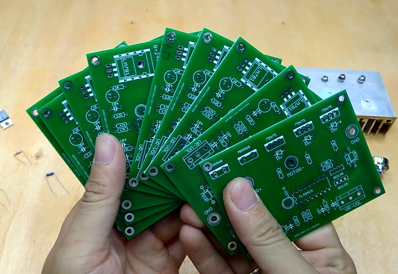
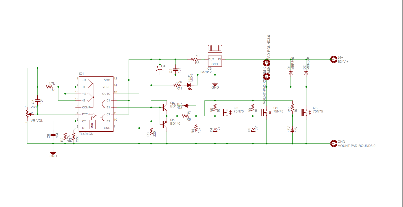
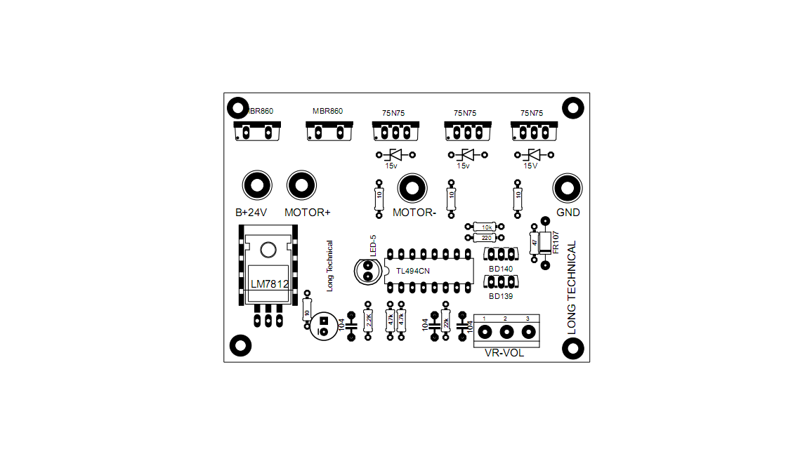
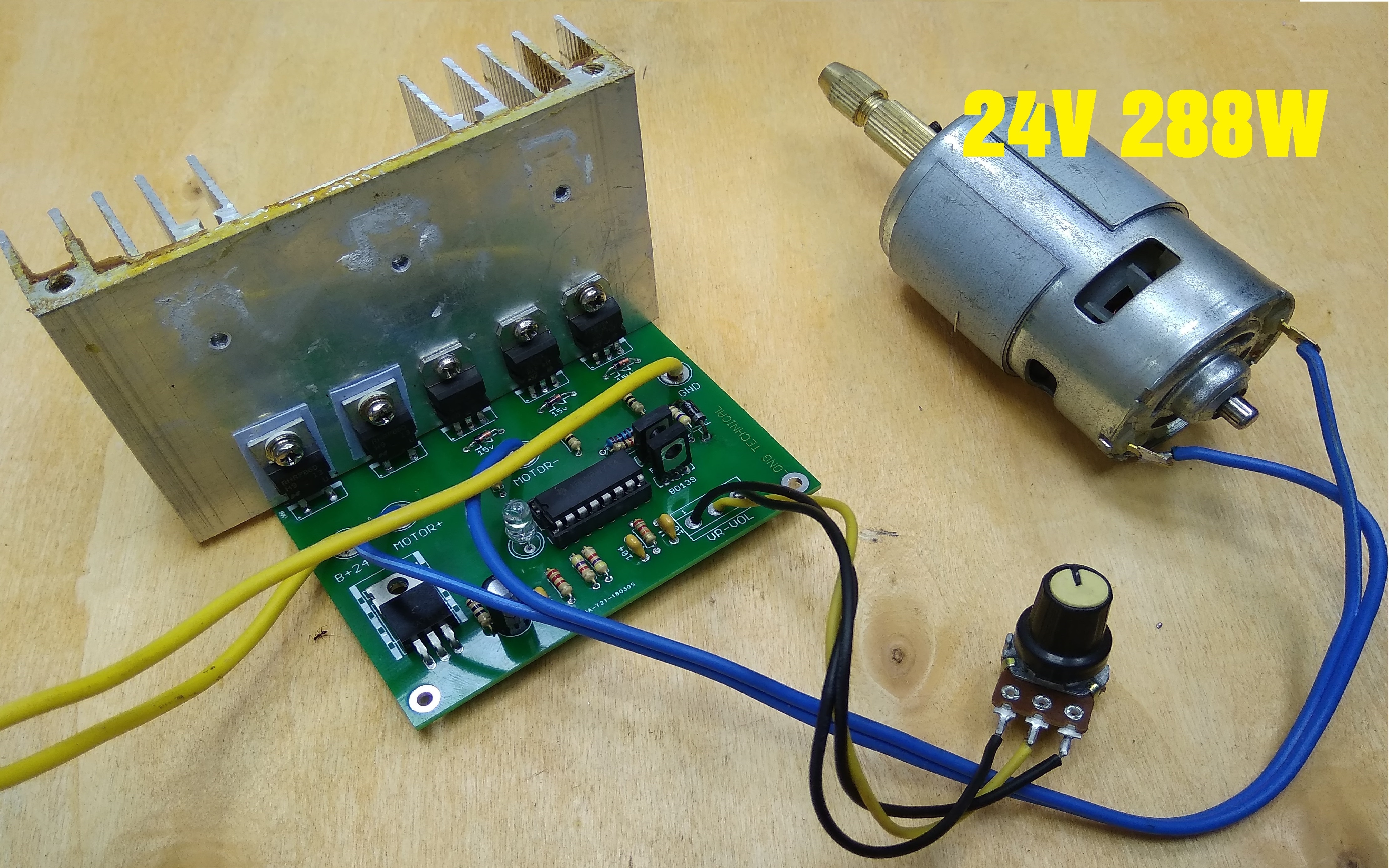
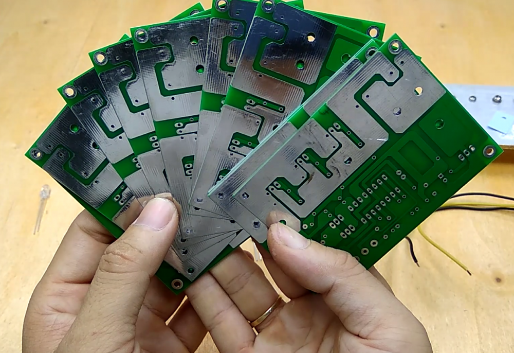
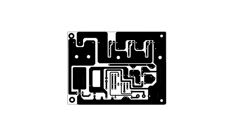
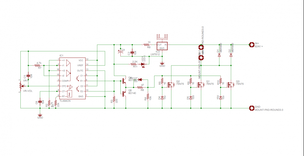
 Introduction ---------------- Hi Friends, I am a newcomer. I try to make 750w DC 24V DC motor speed control. At my project i use TL494 ( ka7500) for control the motor, the current increase by 3 mosfet IRF75n75 ( IFR3205) you can use the biger mosfet for get big power. At this video i show you how to i make it. I don't have the big motor so i use 288W 24V 775 motor for test. You can see the result on my video. The circuit run very well. The total cost of the project is around $10 - $15. Step 1 Hardware Requirement You can see all of my project but i will show again Step 2 Make the PCB You can make the PCB use iron method. I have post the Shematic and PCB file. Please download bellow. Or you can order PCB online like me, i order PCB online from JLCPCB.COM. Their price is very low only 2$/10PCB with high quality. I order PCB from their lot of time. You can try. Look the PCB i had order, what do you think about that ? Step 3 Make the PCB The Schematic and layout file. you can download PDF file below and make it at home by yourself. Step 3 Finsh and Get Big Motor Controler I am a newcomer and this is the fist time i post on this forums. If i have any mistake please comment below i will try to fix in the next project. I want to share you all of thing i know. If you have any question for my project, please comment below i will help you. You can find more project about electrical on my youtube channel: https://www.youtube.com/c/LongTechnical Thank you very much 750W_DC_Motor_Controller_TOP PCB.pdf 750W_DC_Motor_Controller_SCH.pdf 750W_DC_Motor_Controller_PCB.pdf
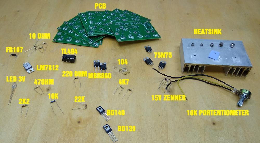


- 7 replies
-
- 1
-

-
- dc motor speed control
- dc motor
- (and 17 more)