Search the Community
Showing results for tags 'relay'.
Found 2 results
-
In this tutorial, you will learn how to create a web server with ESP32 that can control an LED from any device connected to the same WiFi network. You will use the Arduino IDE to program the ESP32 and the web browser to access the web server. What You Need To follow this tutorial, you need the following components: An ESP32 development board A USB cable to connect the ESP32 to the computer The Arduino IDE installed on your computer The ESP32 add-on for the Arduino IDE Get PCBs For Your Projects Manufactured You must check out PCBWAY for ordering PCBs online for cheap! You get 10 good-quality PCBs manufactured and shipped to your doorstep for cheap. You will also get a discount on shipping on your first order. Upload your Gerber files onto PCBWAY to get them manufactured with good quality and quick turnaround time. PCBWay now could provide a complete product solution, from design to enclosure production. Check out their online Gerber viewer function. With reward points, you can get free stuff from their gift shop. Also, check out this useful blog on PCBWay Plugin for KiCad from here. Using this plugin, you can directly order PCBs in just one click after completing your design in KiCad. How It Works The ESP32 will act as a web server that can serve HTML and CSS files to web clients (such as web browsers or smartphones). The web page will have a button that can send an HTTP request to the ESP32 to turn the LED on or off. The ESP32 will also handle the HTTP requests from the web clients and respond accordingly. For example, if the ESP32 receives a request to turn the LED on, it will set the GPIO pin connected to the LED to HIGH and send back a confirmation message. ESP32 Code The code for the ESP32 is also straightforward. You need to include the WiFi.h and ESPAsyncWebServer.h libraries, which are used to connect the ESP32 to the WiFi network and to create the web server. You also need to define the WiFi credentials, the GPIO pin for the LED, and the web server object. Then, you need to create a function to generate the HTML and CSS code for the web page, which will have a button to toggle the LED state. Next, you need to create a function to connect the ESP32 to the WiFi network and print the IP address to the serial monitor. You also need to create a function to handle the HTTP requests from the web clients and change the LED state accordingly. Finally, you need to initialize the LED pin, the WiFi connection, and the web server in the setup() function, and keep the web server running in the loop() function. The complete code is shown below: #include <WiFi.h> #include <ESPAsyncWebServer.h> // WiFi credentials #define WIFI_SSID "Your WiFi SSID" #define WIFI_PASSWORD "Your WiFi Password" // LED pin #define LED_PIN // Web server object AsyncWebServer server(80); // LED state int LED_state = LOW; // Function to generate the HTML and CSS code for the web page String getHTML() { String html = "<!DOCTYPE HTML>"; html += "<html>"; html += "<head>"; html += "<style>"; html += "body {background-color: #F0F0F0; font-family: Arial, Helvetica, sans-serif;}"; html += "h1 {color: #333333; text-align: center;}"; html += "button {width: 150px; height: 50px; font-size: 20px; margin: 10px;}"; html += "</style>"; html += "</head>"; html += "<body>"; html += "<h1>ESP32 Web Server</h1>"; html += "<p>LED state: <span style='color: red;'>"; if (LED_state == LOW) html += "OFF"; else html += "ON"; html += "</span></p>"; html += "<button onclick=\"window.location.href='/led/on'\">Turn ON</button>"; html += "<button onclick=\"window.location.href='/led/off'\">Turn OFF</button>"; html += "</body>"; html += "</html>"; return html; } // Function to connect to WiFi network void connectWiFi() { Serial.print("Connecting to WiFi..."); WiFi.begin(WIFI_SSID, WIFI_PASSWORD); while (WiFi.status() != WL_CONNECTED) { delay(500); Serial.print("."); } Serial.println(); Serial.println("WiFi connected"); Serial.println("IP address: "); Serial.println(WiFi.localIP()); } // Function to handle HTTP requests void handleRequest(AsyncWebServerRequest *request) { // Get the request path String path = request->url(); // Check if the request is to turn the LED on if (path == "/led/on") { // Set the LED pin to HIGH digitalWrite(LED_PIN, HIGH); // Update the LED state LED_state = HIGH; // Send a confirmation message request->send(200, "text/plain", "LED turned on"); } // Check if the request is to turn the LED off else if (path == "/led/off") { // Set the LED pin to LOW digitalWrite(LED_PIN, LOW); // Update the LED state LED_state = LOW; // Send a confirmation message request->send(200, "text/plain", "LED turned off"); } // Otherwise, send the web page else { // Get the HTML and CSS code String html = getHTML(); // Send the web page request->send(200, "text/html", html); } } void setup() { // Initialize the serial monitor Serial.begin(115200); // Initialize the LED pin pinMode(LED_PIN, OUTPUT); digitalWrite(LED_PIN, LED_state); // Connect to WiFi network connectWiFi(); // Start the web server server.onNotFound(handleRequest); server.begin(); } void loop() { // Nothing to do here } Testing the Web Server To test the web server, you need to upload the code to the ESP32 board and open the serial monitor. You should see the IP address of the ESP32, which is something like 192.168.1.8 Then, you need to open a web browser on your computer or smartphone and enter the IP address of the ESP32. You should see the web page with the button to control the LED. You can click the button to toggle the LED state and see the confirmation message on the web browser. Conclusion In this tutorial, you learned how to create a web server with ESP32 that can control an LED from any device connected to the same WiFi network. You learned how to use the WiFi.h and ESPAsyncWebServer.h libraries to connect the ESP32 to the WiFi network and to create the web server. You also learned how to generate the HTML and CSS code for the web page and how to handle the HTTP requests from the web clients. You can use this tutorial as a basis for your own projects that involve controlling GPIO pins or other devices with the ESP32 web server. You can also customize the web page design and functionality to suit your needs. I hope you enjoyed this tutorial and found it useful. If you have any questions or feedback, please let me know. 😊
-
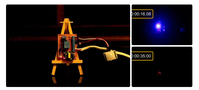
Has this ever happened to you? You come back from a romantic dinner date and when you open the shutter door of your garage you realize that you left the garage light ON. You spent few hours outside with your partner to impress her and all the time this light bulb was on. You immediately turn around and look at her face to see a silent anger on her face. Alright, enough of that. So, in this tutorial, I am going to turn on and off the garage light using a PIR sensor. When the sensor detects a moving object, it turns on the light bulb and when the moving object is gone, it turns it off. Lastly, I am going to make sure that light bulb only turn on during the night time (when its dark). Step 1: Logic In this project, I will be using a PIR sensor along with an LDR to turn on or off a light bulb using a Relay. The things I need to consider before designing the circuit are: - The bulb should only turn on when the room is dark and when a motion is detected. - The bulb should turn off after 30 seconds of the object leaving the sensors proximity. - Most important, we need to place the LDR in a place where it doesn't turn off the bulb as soon as it lights up. Step 2: Hardware For this tutorial we need: A General Purpose PCB 2 x HC-SR501 PIR Sensor 2 x 1N4148 Small Signal Fast Switching Diodes 1 x 1N4007 High Voltage, High Current Rated Diode to protect the micro-controller from voltage spikes 1 x LDR 1 x 10K Trimmer Potentiometer 2 x 470 Ohms Resistor 1 x 10K Resistor 1 x 1K Resistor 1 x 2N3906 General Purpose PNP Transistor 1 x 2N2222 General Purpose NPN Transistor 1 x 5V Relay 1 x LED to display the status 5 x Terminal Blocks 1 x 220V to 5V Buck Step Down Module Few Connecting Cables And General Soldering Equipments Step 3: Assembly Lets first connect the LDR and setup the light detection bit. As we all know we need to setup a voltage divider to use the LDR in a circuit, so, I am adding this 10K POT and 470ohms resistor to setup the voltage divider bit. By adjusting the resistance of the POT we can adjust the intensity of sunlight at which this circuit will operate. Now, lets install the PIR sensor. Connect the VCC to +5v and GND to ground. Then connect the 1N4148 diode to the OUT of the sensor. In this circuit, I am installing just one sensor however in the actual project I have used 2 sensors to capture a bit more than 180 degrees. So, to avoid the sensors from back-feeding each other we need to install a diode to the OUT pin of each sensor. If you want to capture motion at 360 degrees you may need 3 to 4 sensor and diode pair to achieve that. Now that we have the PIR sensor and the LDR in place we need to add the 'AND' functionality. To achieve this I am adding a general purpose PNP transistor. When a motion is detected 'and' when the sunlight is at a certain intensity (adjusted by the POT) current flows out of the transistor. Next, we need to amplify the current received from the collector of the PNP transistor and turn on and off the LED indicator and the Relay. A general purpose NPN transistor is used to achieve this. That's it all done. Step 4: What Have I Have Made So, this is what I have made. On my board components are pretty much soldered everywhere, but you may like to have them nicely installed to give it a bit more cleaner look. OK, so lets check out how this works. Step 5: Demo Alright, I have placed the board on this table to do a quick test. I haven't hooked up a light bulb to the circuit yet. However, the LED indicator should serve the purpose of this demonstration. So, now I am going to turn off the light and make the room dark. Let's see if the sensor picks up motion and lights up the LED. Tada, it works. Now, lets turn on the light of the room and see if the LED indicator turns off or not. Yessss, that works. OK, finally just want to make sure that the light bulb turns off after 30 seconds of me moving out of the sensors proximity. Boom, and that concludes the project. I can now install it on the ceiling and make my partner happy. Instead of having 2 to 3 PIR sensors you can use one and install it at the corner of the wall. However, that will require a fair bit of wiring either inside the roof or on the ceiling, which will be way more expensive and tedious than installing 3 sensors an d putting the device in the middle of the room. You can also swap the Arduino with a NodeMCU board and do a remote data logging to log the time when the sensor detected motion or when the light went on to record when people entered your garage and how long they stayed in there. Step 6: Areas of Applications of PIR Sensors This setup can be used to: * Automate All Outdoor Lights * Automate Lights of Basement, Garden or Covered Parking Areas * Automate Lift Lobby or Common Staircases Lights * Automate bedside or night lamp * Create a Smart Home Automation & Security System and more.. Step 7: Thanks Thanks again for watching this video! I hope it helps you. If you want to support me, you can subscribe to my channel and watch my other videos. Thanks, ca again in my next video.