Search the Community
Showing results for tags 'rheostat'.
Found 1 result
-
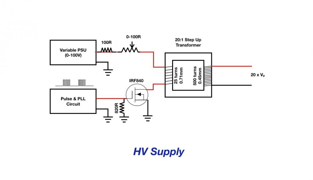
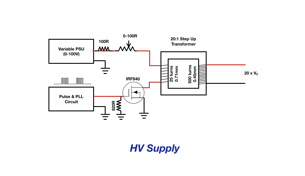
I have a circuit (see pic) that includes the primary winding of a 1:20 self wound transformer. Without some form of additional resistance this circuit will draw too much current from the power supply and damage the FET I’m using so I plan to put a rheostat inline with the primary winding to control the maximum current flowing in it. Given the basic equation for power expended in a resistor of P=I^2R, I’m trying to work out the maximum power rating for the rheostat. If I set the input voltage to 50V and set a 100R rheostat to 50Ohms then my current should be 1.0A. In that case the power rating of the pot will need to be 50W x2 (for de-rating 50% of the track)= 100W i.e. a very beefy rheostat! My query then is this - is it normal practice in circuit design to insert a fixed value resistor, in this case say 100R (as shown), so that the maximum current with the pot at zero is still 0.5A and the max power dissipation 12.5W? On the other hand, if the rheostat is set to zero then will it have no power dissipation capacity at all and be damaged - or are they built differently to potentiometers? Any other thoughts on how I can safely reduce the current flow welcomed. Thank you