Changeover Switch Relay?

sirjimmyd

Nov 3, 2015
9
Joined
Nov 3, 2015
Messages
9
Just want to say thanks in advance for any help I may receive! I am not an electronics guy although I did pass my electronics class with a B. Not great but not horrible either.
I have been beating my head over this problem for about a 2 months and have not yet arrived at a solution. So here I am. I have figured out a way to do it but its just ugly and I know there is an easy solution out there.
So here's the problem:

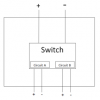
I need a switch that will automatically switch the current to another circuit every time the power is turned on. Here is a crude drawing that I hope helps you visualize the solution:
upload_2015-11-3_14-33-38.png


This is how the switch should run: power on/circuit A is on/power off/power on/circuit B is on/power off/power on/circuit A is on/.......
The power source is 24v and the load is 10amps.
I am using a motor to roll up some plastic and then unroll the plastic on a timer. The motor has a limit switch in it already so we don't need to worry about that.
Is there any product out there that fits the bill?
Thanks
James
 

CDRIVE

Hauling 10' pipe on a Trek Shift3
May 8, 2012
4,960
Joined
May 8, 2012
Messages
4,960
Hello James and a big welcome to EP, where everyone is helpful and friendly.

That said I'm confused as hell. You're correct.. I think this should be simple but your post has no commas, periods, spaces or whatever. I'm confused because I can't separate the segments of your sentence.

Give it another try but please be as clear as possible.

Cheers,
Chris

Edit: Is it possible that you have two circuits and you want one of them to be powered when a voltage source is on but the other is off and visa versa?
 
Last edited:

sirjimmyd

Nov 3, 2015
9
Joined
Nov 3, 2015
Messages
9
Hello James and a big welcome to EP, where everyone is helpful and friendly.

That said I'm confused as hell. You're correct.. I think this should be simple but your post has no commas, periods, spaces or whatever. I'm confused because I can't separate the segments of your sentence.

Give it another try but please be as clear as possible.

Cheers,
Chris

Edit: Is it possible that you have two circuits and you want one of them to be powered when a voltage source is on but the other is off and visa versa?

Chris
I'm glad you recognized my talent for confusion, and thanks for the welcome. Often times I forget that I'm only telling a small percentage of the story! So let's try again.
I think that your last edit nailed it on the head. I have one power source (24v DC) that is on a timer and it needs to control 2 different circuits. Lets call them Circuit A and Circuit B. Basically when the timer turns on the power, then Circuit A is on, and Circuit B is off. Then the timer turns off. The next time the timer turns the power on, then Circuit B is on, and Circuit A is off. Then the timer turns the power off. This time when the timer turns on the power Circuit A is on, and Circuit B is off. This pattern should just continue infinitely.

Is there something out there that does this? Also the load is 10Amps
Thanks
James
 

GPG

Sep 18, 2015
452
Joined
Sep 18, 2015
Messages
452
I am using a motor to roll up some plastic and then unroll the plastic on a timer. The motor has a limit switch in it already
Is it just one motor and you wish to reverse direction each application of power? Are your limit switches already sorted? What is the timing.
 
Last edited:

Colin Mitchell

Aug 31, 2014
1,416
Joined
Aug 31, 2014
Messages
1,416
You just need a flip flop and a relay. But you need to start with a circuit and then work on improving the circuit until it is correct.

You need the circuit powered all the time and the logic (the commands) comes from the timer to turn the motor ON and OFF.
 

CDRIVE

Hauling 10' pipe on a Trek Shift3
May 8, 2012
4,960
Joined
May 8, 2012
Messages
4,960
I have one power source (24v DC) that is on a timer and it needs to control 2 different circuits.
James

Does this mean that your circuit currently incorporates a timer that's turning a single load (motor) on and off?

Chris
 

AnalogKid

Jun 10, 2015
3,056
Joined
Jun 10, 2015
Messages
3,056
You can do exactly what you want with nothing but relays.

What you want is a stepper relay, an old part way out of favor these days. Unlike a normal relay, a stepper relay armature does not switch the current to the load. It actuates a rotary cam that moves a switch that controls the current. So when power is off the cam holds the switch in its last position, and when the coil is energized the cam moves to the next position, usually toggling a SPDT switch to the other pole. You would need two power relays to control the load (or one DPDT relay with the right contact rating), and the stepper would control the power relays. No electronics, infinite memory. Check industrial distributors and on ebay for stepper relay or stepping relay.

Most generic stepper relays are two-position. A 10 position stepper relay was the basis for every rotary phone system in the world before those little transistors took over everything.

EDIT: Learned a new term today: impulse relay

http://www.digikey.com/product-detail/en/1393134-1/PB1359-ND/1127759

SPDT or DPDT 15 A contacts, but rated for only 1/2 A DC (common with this switch type) so you still might need a true DC-rated DPDT relay for the load. Note, many DPDT relays have different ratings for the NC contacts vs. the NO contacts. This is because the armature spring force that makes the NC contacts closed is much less than the coil force that makes the NO contacts closed.

ak
 
Last edited:

CDRIVE

Hauling 10' pipe on a Trek Shift3
May 8, 2012
4,960
Joined
May 8, 2012
Messages
4,960
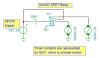
Perhaps I'm misreading your requirements and what AK posted is what you need.

In the event that I'm not misunderstanding you I think a SPDT relay is what you need.

Chris
upload_2015-11-4_9-34-38.png
 

Alec_t

Jul 7, 2015
3,821
Joined
Jul 7, 2015
Messages
3,821
I second the use of an impulse relay (driving secondary relays or contactors or SSRs).
Is 10A the motor run current or its stall current?
 

AnalogKid

Jun 10, 2015
3,056
Joined
Jun 10, 2015
Messages
3,056
CDRIVE - I think SW 1 connects to VS1 before any other connection, including a power feed to the relay armature.

ak
 

sirjimmyd

Nov 3, 2015
9
Joined
Nov 3, 2015
Messages
9
Is it just one motor and you wish to reverse direction each application of power? Are your limit switches already sorted? What is the timing.
Yes it is just one motor and I need it to go forward and reverse. The motor has 2 limit switches in it so that is all taken care of.
What do you mean by what is the timing?
thanks
 

sirjimmyd

Nov 3, 2015
9
Joined
Nov 3, 2015
Messages
9
Does this mean that your circuit currently incorporates a timer that's turning a single load (motor) on and off?

Chris
No the motor has 2 limit switches so it turns off automatically. What I am trying to do is to get the motor to reverse by switching polarities.

Basically I'm just confused! The more I delve the more I get confused. This is a good thing because I'll end up smarter for it!
Thanks
 

sirjimmyd

Nov 3, 2015
9
Joined
Nov 3, 2015
Messages
9
You can do exactly what you want with nothing but relays.

What you want is a stepper relay, an old part way out of favor these days. Unlike a normal relay, a stepper relay armature does not switch the current to the load. It actuates a rotary cam that moves a switch that controls the current. So when power is off the cam holds the switch in its last position, and when the coil is energized the cam moves to the next position, usually toggling a SPDT switch to the other pole. You would need two power relays to control the load (or one DPDT relay with the right contact rating), and the stepper would control the power relays. No electronics, infinite memory. Check industrial distributors and on ebay for stepper relay or stepping relay.

Most generic stepper relays are two-position. A 10 position stepper relay was the basis for every rotary phone system in the world before those little transistors took over everything.

EDIT: Learned a new term today: impulse relay

http://www.digikey.com/product-detail/en/1393134-1/PB1359-ND/1127759

SPDT or DPDT 15 A contacts, but rated for only 1/2 A DC (common with this switch type) so you still might need a true DC-rated DPDT relay for the load. Note, many DPDT relays have different ratings for the NC contacts vs. the NO contacts. This is because the armature spring force that makes the NC contacts closed is much less than the coil force that makes the NO contacts closed.

ak
Stepper relay! Dang that sounds like just the thing. Sometimes mechanical is the best!
 

sirjimmyd

Nov 3, 2015
9
Joined
Nov 3, 2015
Messages
9
Perhaps I'm misreading your requirements and what AK posted is what you need.

In the event that I'm not misunderstanding you I think a SPDT relay is what you need.

Chris
View attachment 22971
Sweet drawing! Reminds me of that electronics class. It's all slowly coming back.

So the SPDT relay will switch the power to DCM1 while DCM2 is off. And the vice versa when the power is switched on again the next time?
Thanks
 

sirjimmyd

Nov 3, 2015
9
Joined
Nov 3, 2015
Messages
9
I second the use of an impulse relay (driving secondary relays or contactors or SSRs).
Is 10A the motor run current or its stall current?
Everytime I see those words like impulse relay, SSR... I get a bit intimidated! I am not an electronics guy yet. I can wire a house no problem but electronics is some serious stuff. It reminds me of programming in FORTRAN 90. Very logic oriented and cool as hell!!!

The 10A is the motor run current. What is "stall current"?
Thanks
 

CDRIVE

Hauling 10' pipe on a Trek Shift3
May 8, 2012
4,960
Joined
May 8, 2012
Messages
4,960
No the motor has 2 limit switches so it turns off automatically. What I am trying to do is to get the motor to reverse by switching polarities.

Your requirements would have been made much clearer if you had stated this in post 1. :rolleyes:

Chris
 

sirjimmyd

Nov 3, 2015
9
Joined
Nov 3, 2015
Messages
9
Your requirements would have been made much clearer if you had stated this in post 1. :rolleyes:

Chris
Count yourself lucky. Can you imagine what my poor wife goes through on the daily?!?
So if I wanted a switch that reverses the polarity at each application of power, what would I need?
Thanks
 

CDRIVE

Hauling 10' pipe on a Trek Shift3
May 8, 2012
4,960
Joined
May 8, 2012
Messages
4,960
Count yourself lucky. Can you imagine what my poor wife goes through on the daily?!?
So if I wanted a switch that reverses the polarity at each application of power, what would I need?
Thanks
There probably more ways to do that then I care to count. They would all be solid state though. The simplest way would be what AK posted and is being discussed.

Chris
 

Alec_t

Jul 7, 2015
3,821
Joined
Jul 7, 2015
Messages
3,821
The 10A is the motor run current. What is "stall current"?
Stall current is the current when the motor is stalled (i.e stationary) but power is applied, such as at start-up. It is many (perhaps 5 or more) times the running current (i.e. the current when the motor is up to full speed). Your relay contacts need to be rated to handle at least the stall current with the inductive load constituted by the motor.

Edit: The relay in that link will be unsuitable. Despite the word 'step' in the ad it looks like a normal SSR with a single triac output and is rated at only 10A.
 
Last edited:
Top