Relay

Stoneww

Apr 18, 2017
42
Joined
Apr 18, 2017
Messages
42
Hey I've been trying my best to get this relay circuit working for about a week now, help would be very much appreciated :)

I've managed to get the comparator working as well as the transistor. However the transistor wasn't enough to power a motor. I've tried the motor with a relay but even after numerous guides I couldn't do it. As I understand the principle is that if the coil is powered an EM field will pull a switch and activate a circuit which has a different power source.

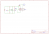
I haven't been able to successfully connect this on my breadboard. Could anyone show me how it would be done? Below is a circuit diagram of how I think it works and also a diagram I used as a reference.
Relay.png
relay-light.jpg
 

Attachments

  • Relay.png
    Relay.png
    41 KB · Views: 149

Harald Kapp

Moderator
Moderator
Nov 17, 2011
14,271
Joined
Nov 17, 2011
Messages
14,271
Your diagram is o.k.
What's missing is: where does IO1 or IO2 come from? This should be a signal that switches between 0 V (relay on) and open circuit (relay off). An I/O port of a microcontroller will not work. You'll need a more powerful driver, e.g. a transistor.

By the way: do not use the breadboard for the mains side of the relay. A breadboard isn't menat to be used with mains voltage. Use some wire and solder it t o the relay's terminals, then connect only the coil side to the breadboard.
 

Minder

Apr 24, 2015
3,561
Joined
Apr 24, 2015
Messages
3,561
The .png pic shows it, you could also use a 2n7000 fet if driven from a comparitor.
M.
 

Stoneww

Apr 18, 2017
42
Joined
Apr 18, 2017
Messages
42
Your diagram is o.k.
What's missing is: where does IO1 or IO2 come from? This should be a signal that switches between 0 V (relay on) and open circuit (relay off). An I/O port of a microcontroller will not work. You'll need a more powerful driver, e.g. a transistor.

By the way: do not use the breadboard for the mains side of the relay. A breadboard isn't menat to be used with mains voltage. Use some wire and solder it t o the relay's terminals, then connect only the coil side to the breadboard.

Oh dude not that diagram, I mean't the diagram that I have left as an attachment
 

AnalogKid

Jun 10, 2015
3,045
Joined
Jun 10, 2015
Messages
3,045
The circuit will work better if you swap the two comparator inputs (to change the output logic polarity to go high when you want the motor to run) change the transistor to an NPN (with base resistor) or N-channel MOSFET (2N7000, 7002). The gate or emitter goes to GND and the collector or drain goes to the coil. This drives the relay with a saturated switch instead of an emitter follower. This reduces power dissipation in the transistor and puts more voltage across the relay coil.

ak
 

duke37

Jan 9, 2011
5,364
Joined
Jan 9, 2011
Messages
5,364
You need a npn transistor (2N2222) or n channel fet.(2N7000)

Edit. Nothing like saying the same thing twice:)
 

Stoneww

Apr 18, 2017
42
Joined
Apr 18, 2017
Messages
42
The circuit will work better if you swap the two comparator inputs (to change the output logic polarity to go high when you want the motor to run) change the transistor to an NPN (with base resistor) or N-channel MOSFET (2N7000, 7002). The gate or emitter goes to GND and the collector or drain goes to the coil. This drives the relay with a saturated switch instead of an emitter follower. This reduces power dissipation in the transistor and puts more voltage across the relay coil.

ak
Thanks for the help :) , turns out the problem was just that 9V wasn't enough for the coil but 18V did the trick.
 
Top