Hello,
I'm working on a project to measure distance using ultrasonic sensor and Arduino Mega. I'm using 2 LCDs for output distance in mm. A separate 5V (1A or 2A) power supply unit is used for LCDs power supply.
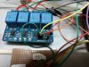
The circuit uses 5V all over. The tower lamp connected to NO/NC contacts of 2 channel relay is 230V AC 50hz.
The LCDs are working fine when ultrasonic sensor gives initial sensing output, but after few seconds the LCD displays are blank (other functions are working fine as programmed). I have connected Arduino ground and 5V power supply ground in my circuit.I tried disconnecting tower lamp (230 V) from circuit, but displays are okay until i switch on any load (i.e room fan,light,heater). Not sure what is going on . There are no relation between relay output pins and the fans and tube lights.
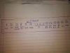
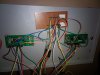
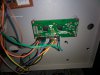
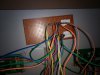
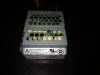
The attached picture shows the pin numbers of LCD and respective supply voltage. Can you please help me fix this issue? Please let me know if you need any details.
I'm working on a project to measure distance using ultrasonic sensor and Arduino Mega. I'm using 2 LCDs for output distance in mm. A separate 5V (1A or 2A) power supply unit is used for LCDs power supply.
The circuit uses 5V all over. The tower lamp connected to NO/NC contacts of 2 channel relay is 230V AC 50hz.
The LCDs are working fine when ultrasonic sensor gives initial sensing output, but after few seconds the LCD displays are blank (other functions are working fine as programmed). I have connected Arduino ground and 5V power supply ground in my circuit.I tried disconnecting tower lamp (230 V) from circuit, but displays are okay until i switch on any load (i.e room fan,light,heater). Not sure what is going on
. There are no relation between relay output pins and the fans and tube lights. The attached picture shows the pin numbers of LCD and respective supply voltage. Can you please help me fix this issue? Please let me know if you need any details.