I believe
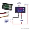
@Bluejets is correct. These el-cheapo meters do share a common ground with the meter supply (thin red and black wires). They also
do not measure negative voltages or negative currents with respect to "ground".
Here is a link to a rather lengthy discussion of how (and how NOT) to wire these puppies into your circuit.
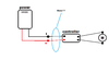
With regard to PWM motor control... PWM is a unipolar train of pulses, possibly reversing in polarity to change motor direction. Motor speed, OTOH, is determined by the duty cycle of the PWM signal applied. Zero duty cycle means no pulses, and therefore no voltage or current is applied to the motor. A one-hundred percent duty cycle also means no pulses, but with output voltage present and constant all the time. Any duty cycle in between 0% and 100% will produce an
average voltage and an
average current that is between zero and the maximum voltage/current that the PWM controller can provide. If you want to display this average voltage (or current) on a DC-responding meter, you must filter out the fundamental PWM switching frequency, and ideally all of its harmonics. However, usually all you need is a low-pass series resistor-parallel capacitor RC filter... something on the order of one thousand ohms and a few dozen microfarads will probably work. You can add increased capacitance if there is still too much "bounce" in the digital readout, but be careful if increasing the resistance... many of these imported meters have a relatively low input impedance which will lead to measurement errors if the resistance in series with the meter input is increased too much.
An oscilloscope is a virtual necessity when trying to troubleshoot pulse circuits. I would suggest you obtain an inexpensive one and learn how to use it. You may find, as I did in the previous century, that an oscilloscope is your "go to" test equipment, second only to your digital multimeter in usefulness. IIRC, my first o'scope was about a hundred bux or so in the 1960s. Much better, less expensive, more portable, new models are available today. My last purchase was for a digital storage oscilloscope (DSO) that cost less than three hundred dollars with free shipping.
All of this test equipment stuff is made much less expensively in Asia and Pacific Rim countries such as India, South Korea, China, and Japan, but you need to be careful which "brand" to purchase. Surf the Internet and visit support groups such as Electronics Point to get some advice on what to purchase and how much you should expect to pay for it. I usually buy only from a USA-based distributor who offers a "money back" guarantee if I am unsatisfied with my purchase, but your mileage (or kilometers) may differ.