Kenwood TS 830S

danadak

Feb 19, 2021
1,104
Joined
Feb 19, 2021
Messages
1,104
Was the original cathode R a 2W R. Some designs in RF amps use lower wattage
Rs to act as safety fuses.

Regards, Dana.
 

shri

Jul 28, 2022
8
Joined
Jul 28, 2022
Messages
8
But I live in Berlin, there are no smaller ones in the store. The original ones are 1/2 watt but they are as big as the modern 2 watt ones. What does that have to do with the problem?
 

danadak

Feb 19, 2021
1,104
Joined
Feb 19, 2021
Messages
1,104
But I live in Berlin, there are no smaller ones in the store. The original ones are 1/2 watt but they are as big as the modern 2 watt ones. What does that have to do with the problem?

Just a caution, it is for protecting the finals.

Caps on the finals not come loose, I have had that happen. Screen supply
correct. When you key down on rig you see no change in scope pics at
grids, plate....?

Coax cable to dummy load good ? I have had problems with cheap Chinese knockoffs.

Any screw fittings in dummy load good.PA ground trace to chassis solid. PA plate
inductors, wound around the 1W R, their solder joints look good ?

iu


The verical L in front I had a solder joint go hi z on one.

http://www.wb4hfn.com/KENWOOD/Articles/TS-830 Survival Guide-01.pdf
Comment in above about using 6146W tunes as finals.


Regards, Dana.
 
Last edited:

shri

Jul 28, 2022
8
Joined
Jul 28, 2022
Messages
8
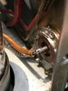
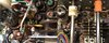
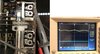
I have not changed the cathode resistors on the final stage. They are 4x20ohm and are not damaged. The transceiver came with these tubes for repair, I have not changed anything. As I said above, I tried the tubes on another transceiver to check if they were OK. In the photo you can see the new resistors, the ones with pink color. The entire P filter was disassembled to clean the switch. All solder is fine. I ran a safety wire between the antenna jack and the ground on the end stage. The band selector works correctly, the capacitors in the P filter have been measured and have no deviations from their nominal values. Survival Guide I read it. Thanks for the reply Dana.IMG_2384.JPG IMG_2385.JPG
 

shri

Jul 28, 2022
8
Joined
Jul 28, 2022
Messages
8
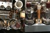
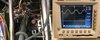
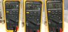
IMG_2387.JPG IMG_2390.JPG IMG_2395.JPG IMG_2392.JPG
1 picture drosel ok, 2 picture mixer PT4 2,6V, 3 picture exit DRV point 260mV, 4 picture anod driver tube RX 336V TX 3,03V and HV 984V
 
Last edited:

shri

Jul 28, 2022
8
Joined
Jul 28, 2022
Messages
8
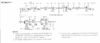
Yes, I saw that first. That's where the problem is. As per the diagram, 2.1Vpp comes out of the mixer, but 250mV comes out of the anode. Very strange as if there is a transmission mode short circuit. Actually, there isn't. If there were leakage capacitors in the circuit of the 12BY7A, it should also give incorrect voltages on RX. At the same time, the voltages of G1 -46V-RX, +0.6V-TX and G2 +262V are normal on both RX and TX. It seems that a very large current flows through the tube on the TX, as if it is damaged. But when I put it on the other transceiver it works properly. If there is a short in the variable capacitor or a problem in the resonant circuits, the tube should simply amplify not, but not lose its anode voltage???......
 

danadak

Feb 19, 2021
1,104
Joined
Feb 19, 2021
Messages
1,104
Yes, I saw that first. That's where the problem is. As per the diagram, 2.1Vpp comes out of the mixer, but 250mV comes out of the anode. Very strange as if there is a transmission mode short circuit. Actually, there isn't. If there were leakage capacitors in the circuit of the 12BY7A, it should also give incorrect voltages on RX. At the same time, the voltages of G1 -46V-RX, +0.6V-TX and G2 +262V are normal on both RX and TX. It seems that a very large current flows through the tube on the TX, as if it is damaged. But when I put it on the other transceiver it works properly. If there is a short in the variable capacitor or a problem in the resonant circuits, the tube should simply amplify not, but not lose its anode voltage???......

Your scope is capable of seeing 50 - 100 Mhz oscillation, eg. if its not neutralized ?
Probe not stopping osc because of its C....so you never see it.....?

Of course you would see rig current draw jump when you put it on CW...

I have been looking for the W version of tube info, I read some time ago they were
problems in some of the Kenwoods, do not remember why. Something sticks in the
back of my mind on this....

This has some interesting comments - https://www.tubesandmore.com/tech-articles/6146-family-tubes

Here they show "not recommended" https://www.rfparts.com/tubes/tubes-6146.html?p=1

https://www.rfparts.com/tubes/tubes-6146/6146w-tung-sol-transmitting-tube-not-for-kenwood.html

But this thread seems to dispel any problems - https://antiqueradios.com/forums/vi...sid=cb0bf93ddb33e99d077dfea7c1eb2835&start=20

The CAR control and ALC look right.....?


Regards, Dana.
 
Last edited:

shri

Jul 28, 2022
8
Joined
Jul 28, 2022
Messages
8
Yes, I saw that first. That's where the problem is. As per the diagram, 2.1Vpp comes out of the mixer, but 250mV comes out of the anode. Very strange as if there is a transmission mode short circuit. Actually, there isn't. If there were leakage capacitors in the circuit of the 12BY7A, it should also give incorrect voltages on RX. At the same time, the voltages of G1 -46V-RX, +0.6V-TX and G2 +262V are normal on both RX and TX. It seems that a very large current flows through the tube on the TX, as if it is damaged. But when I put it on the other transceiver it works properly. If there is a short in the variable capacitor or a problem in the resonant circuits, the tube should simply amplify not, but not lose its anode voltage???......


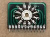
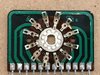
Thank you very very much for your help. But I'm a big fool. The moment I wrote the last post I realized where the problem was. Thanks to DANA for making me read the Survival Guide a second time. As they said, my first job was to clean the band switch, so I didn't doubt it, but! I forgot to check........
" Cause: The bandswitch (also) has dissimilar-metal crimp-connections that turn into semi- insulators
due to electrolysis. This takes place between the bandswitch's riveted-on,, tin-plated, stationary
contacts and the copper-foil on the printed circuit board [PCB]. Fix: Apply a small amount of
conductive-paint where the stationary switch contact touches the copper-foil on the PCB. The
conductive-paint will be drawn, by capillary-action, into the problem area where the two,
dissimilar-metals touch each other."
I shorted a band switch with one wire. And "Eureka" the voltage of the anode came to TX. I have now disassembled the band switch again and resoldered all the crimp-connections. When I put everything back together I will write about the result. There may be other problems, but this one will be solved for sure. Best regards to all and thank you very much for making me think more deeply about where the problem lies.
 
Last edited:
Top