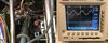
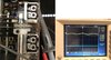
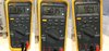
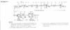
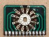
Yes, I saw that first. That's where the problem is. As per the diagram, 2.1Vpp comes out of the mixer, but 250mV comes out of the anode. Very strange as if there is a transmission mode short circuit. Actually, there isn't. If there were leakage capacitors in the circuit of the 12BY7A, it should also give incorrect voltages on RX. At the same time, the voltages of G1 -46V-RX, +0.6V-TX and G2 +262V are normal on both RX and TX. It seems that a very large current flows through the tube on the TX, as if it is damaged. But when I put it on the other transceiver it works properly. If there is a short in the variable capacitor or a problem in the resonant circuits, the tube should simply amplify not, but not lose its anode voltage???......
Thank you very very much for your help. But I'm a big fool. The moment I wrote the last post I realized where the problem was. Thanks to DANA for making me read the Survival Guide a second time. As they said, my first job was to clean the band switch, so I didn't doubt it, but! I forgot to check........
" Cause: The bandswitch (also) has dissimilar-metal crimp-connections that turn into semi- insulators
due to electrolysis. This takes place between the bandswitch's riveted-on,, tin-plated, stationary
contacts and the copper-foil on the printed circuit board [PCB]. Fix: Apply a small amount of
conductive-paint where the stationary switch contact touches the copper-foil on the PCB. The
conductive-paint will be drawn, by capillary-action, into the problem area where the two,
dissimilar-metals touch each other."
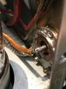
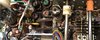
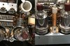
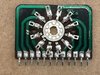
I shorted a band switch with one wire. And "Eureka" the voltage of the anode came to TX. I have now disassembled the band switch again and resoldered all the crimp-connections. When I put everything back together I will write about the result. There may be other problems, but this one will be solved for sure. Best regards to all and thank you very much for making me think more deeply about where the problem lies.