Sallen Key Low Pass Filter, bandpass filter

bertus

Moderator
Nov 8, 2019
3,836
Joined
Nov 8, 2019
Messages
3,836
Hello,

Yes, The point called REF is the virtual ground.
All points called REF are connected together.
The ground is lifted to about hlf the powersupply.

Bertus
 

Maglatron

Jul 12, 2023
2,025
Joined
Jul 12, 2023
Messages
2,025
that easy, just connect the points called ref, for the virtual, and then what about the part in the red box
 

Attachments

  • ref.png
    ref.png
    29.6 KB · Views: 2

bertus

Moderator
Nov 8, 2019
3,836
Joined
Nov 8, 2019
Messages
3,836
Hello,

The circuit in the red box, is the circuit to create the REF voltage.
On the input of that opamp there is a voltage divider that creates half the powersupply.
The opamp is used as buffer.

Bertus
 

Maglatron

Jul 12, 2023
2,025
Joined
Jul 12, 2023
Messages
2,025
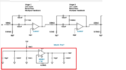
can I use the TL074 for the buffer, and I think I understand it, do you use the same 12v going into the filters op-amps as the input for the buffer and then connect the refs together as you said before? also can you use this buffer for all of the filters or do you need to create a buffer for each filter that's been made? because I ordered quad op-amps to cater for the 4 op amps in each filter but now there is a 5th op-amp for the buffer
 
Last edited:

Maglatron

Jul 12, 2023
2,025
Joined
Jul 12, 2023
Messages
2,025
I ordered quad op-amps to cater for the 4 op amps in each filter but now there is a 5th op-amp for the buffer
do I need to make this buffer circuit for every filter also or can I use the the one buffer circuit for all of the reference ground on each and every filter as I will be using the same 12v source or all of the filters
 

Maglatron

Jul 12, 2023
2,025
Joined
Jul 12, 2023
Messages
2,025
I ordered quad op-amps to cater for the 4 op amps in each filter but now there is a 5th op-amp for the buffer
do I need to make this buffer circuit for every filter, also or can I use the the one buffer circuit for all of the reference ground on each and every filter as I will be using the same 12v source or all of the filters
On the input of that opamp there is a voltage divider that creates half the powersupply. (would this be 6v)
The opamp is used as buffer. so the reference voltage (is 6v at virtual ground) and the actual ground connects through the buffer to ground so positive (12v for positive)(ref gnd 6v) and ground(0v for negative) and for the buffer circuit can I still use the TL074
 
Last edited:

bertus

Moderator
Nov 8, 2019
3,836
Joined
Nov 8, 2019
Messages
3,836
Hello,

No, one buffer is likely enough for several filters.

Bertus
 

Maglatron

Jul 12, 2023
2,025
Joined
Jul 12, 2023
Messages
2,025
I have the paper now so am going to commence in designing all of the required frequency filters what should thee gain of the passband be?
 

Maglatron

Jul 12, 2023
2,025
Joined
Jul 12, 2023
Messages
2,025
is gain the ratio of the input frequency to the output frequency?
 

Maglatron

Jul 12, 2023
2,025
Joined
Jul 12, 2023
Messages
2,025
just to clarify and make crystal clear what are these parameters you can set in the red box
 

Attachments

  • what these represent.png
    what these represent.png
    133.8 KB · Views: 3

Maglatron

Jul 12, 2023
2,025
Joined
Jul 12, 2023
Messages
2,025
what are the differences do ie changing -3 dB to -6 dB in the pass band, changing the stopband from -40 to -10 what will be the real world effects?
And what would be better for what I'm trying to do eg filter sound waves


1701292550427.png
1701292618209.png
 
Top