Sir Artmakersworld . . . . . . . .
Esssssssssssssssssss
My revelation attempts are being only as good as your initial supplications content and feedback.
This time around . . . in relating to the original headlamp . . . initially.
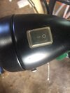
The top down headlamp shot does reveal a nice, thick clear molded vinyl cover.
That switch initially appears to be a common ROCKER SWITCH and is having its two halves marked with the on-off symbols and using the second photo, it only has two connections, so that would define it as a S
ingle P
ole S
ingle T
hrow electrical category. Pressing down on the high side rocks it down and transitions between its on /off states, each time.
THEN . . . I look at your unit again . . . .HEY! . . . . . . both sides of YOUR switch are being up equally level.
So o o o o o o o . . . .it looks like your level bar just pushes straight down and has compression spring return to bring it back up as it is released. The symbolization is now relating to its dual on and off functionality.
In actuality, its momentary contact action connects to related digital/logic/power switching circuitry to engage sequential multi functions/effects.
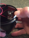
On that testing of the existing switch . . . . . MY mindset . . . . . would NOT be tracking down , cutting and baring the ends a length of hook up wire !
Instead, I'd be reaching for the closest chromed or nickel plated nail clippers, envelope opener, pocket knife blade, tweezers, etc. and jumper across that switches exposed terminals. There should then be light emanating in its sequenced different modes at each shorting.
Should this not work . . . . move to the battery holder to analyze.
HERE ARE MY FINDINGS . . . . .
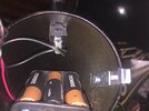
Photo 2 reveals the holder and its installed 3 cells of the batt pack.The far right cell reveals that the "copper" top stripes are on the + end of the cell.
The mid cell confirms that these are AA size vice . . .possibly . . . AAA. . . . and its dating also tells us that these are FRESH!
BARELY visible . . . at left front corner of the holder is a splayed out hollow rivet which is associated with connecting into the red wire of the red and black pair shown at the left.
Refer to the top photo reference and see the formed springed contact jumper which I am expecting to be installed down at the - end of the left cell . It will be using its compression spring end under it, while the spring jumping wire is spanning over to its flat spiral contact which will mate with the + end of the center cell.
Come to the front to the center cell + contact and another like spring jumper connects to the far right cells + connection.
3rd rear cell uses another splayed hollow rivet to connect into the black wire.
Confirm if this checks out on the batt holder.
Caveat . . . . .
Watch out for that right half tapered compression spring in the top illustration . . . as its right cone can make a sloped diagonal positional transition and mess wit' 'cher MIND ! Its being an opti-ca-ful collusion !
EUREKA . . . . . AN OBSERVATION
Observe photo 2 of the battery holder, at its absolute lower left frontal corner.
This unit has been in HOT environs and had this prior installed cell . . . or more of them . . . rupture and let its alkaline electrolyte fill " weep and creep " .
As can be seen, it was being long and severe acting enough to have had the alkali react with the nickel plated brass and eat away and leave blobs of blue green CuSo4 .
Confirm if a clear hardened layer of insulative alkalinic crud has formed on the other sides connections. Check all the other cells connections for the same probability
Let's now switch to the . . . . other
OLDE TIMEY SWITCH . . . . . THAT YOU FOUND ON THE "GIFTED" BIKE HEADLAMP
How in the wurld dids you 'spects me to knose that switch had a lever knob on its ?
Untils I gots yer noo pick-choors !
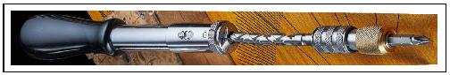
I captured the best to images from your video and that now reveals that no spiral
shaft is needed as you have a lever knob and that directly produces rotary action.
But it DOES look like that whole stacked cluster is loose and not being tight enough.
When you pressed in on the end cap, some degree of functionality was then possible.
The better photo did reveal that a slanted parallax error made the first photo appear to have 4 rotary contact cups. My new photo is confirming only 3 contact cups, being rotationally distributed at 120 degrees.
PLUS you can see the 2 mating brass "super rivets" contacts mounted on the phenolic blank, in a bit different positions, than originally perceived. You can now also see that they have large holes in their center, that the cup contacts fall into. As well, there are being additional intermediate spaced out holes drilled around the phenolic disc as stop divots. As you rotate the cup contact triage, the cups consecutively fall down into 3 divot sets, thus giving a definite indexing and feel as to where they stop and fall down into holes..
Since your lever knob is producing shaft rotation, I'm sort of expecting there to be a ratcheting gear under that knob to move a defined distance as you rotate the knob. See the illustration of the ratcheting gear and figure the crank as being your lever knob And the the gear slant distance determines the degree of rotation until a cup rotates, stops and falls down into indexing divots. With 3 contact cups (on) and 3 dead spaces (offs) a 6 tooth ratcheting gear would be needed.
Should you take out that cotter pin and let the compressed parts come apart, you likely will see the problem section being associated with the knob and any now unviewable parts inwards to the rear viewable parts that we can view, of which, all of that back section, seems in order.
I think that you should pull that cotter pin and slip all apart and investigate.
PICK-CHOORS . . . . .
View attachment 64146
Thaaaaaasssssit . . . . .
73's de Edd . . . . . . . . . .
.


.jpeg")