Is This Really a 470nF 400V ceramic capacitor ?

SevMamba

Oct 24, 2024
3
Joined
Oct 24, 2024
Messages
3
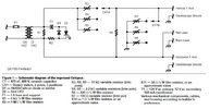
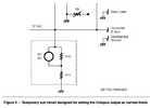
Hi, I am trying to build an Octopus Curve Tracer from this circuit diagram (see attached file). I'm usually ok building stuff when I have a circuit diagram, but not good at all in designing circuits. I chose this design as it looks fairly simple and has a defined set of components, BUT the parts lists calls for the capacitor C1 to be a 470 nF, 400V, ceramic capacitor. I have been unable to purchase one. The symbol on the diagram shows a polarised capacitor but my research says ceramic capacitors are non-polarised. Looking for a 470nF 400V capacitor brings up a CCB type. My question is, Is This Really a 470nF 400V ceramic capacitor ? or should it be something else.
Thanks, Sev
 

Attachments

  • Screenshot 2024-10-24 175207.png
    Screenshot 2024-10-24 175207.png
    57.3 KB · Views: 10

Alec_t

Jul 7, 2015
3,817
Joined
Jul 7, 2015
Messages
3,817
Welcome to maker.pro!
Both C1 and R2 have the wrong values if they're driven by the 12V secondary of the transformer and the LED is intended as a 'power on' indicator.
 

73's de Edd

Aug 21, 2015
3,730
Joined
Aug 21, 2015
Messages
3,730
Sir Sev Mamba . . . . .

I tracked this circuit down to both a You Tube presentation and a foreign language write up under Scrib -d.
The circuit is the same.

The YELLOW ENCOMPASSED components are there merely for creating a pilot light
Change to the other circuit . . .below it
1729770553602.png
ADDITIONALLY . . . . .

Since you have the complete article . . . . . . .I'm still looking for GREEN boxed R11 resistor ? ? ?
PLUS . . . ." IMPROVED" . . . . . .Frankly, I can't see any difference from the 1960's circuit and using an OS-8 un triggered /free running Oscilloscope. .

73's de Edd . . . . .
1729771185398.png
 
Last edited:

SevMamba

Oct 24, 2024
3
Joined
Oct 24, 2024
Messages
3
Sir Sev Mamba . . . . .

I tracked this circuit down to both a You Tube presentation and a foreign language write up under Scrib -d.
The circuit is the same.

The YELLOW ENCOMPASSED components are there merely for creating a pilot light
Change to the other circuit . . .below it
View attachment 65050
ADDITIONALLY . . . . .

Since you have the complete article . . . . . . .I'm still looking for GREEN boxed R11 resistor ? ? ?
PLUS . . . ." IMPROVED" . . . . . .Frankly, I can't see any difference from the 1960's circuit and using an OS-8 un triggered /free running Oscilloscope. .

73's de Edd . . . . .
View attachment 65051
Thank you for your response, when looking for R11 did you mean where is it used or where can you buy a 50ohm resistor? It seems as if the article and circuit diagram are not as good as I first thought. Should I make it and hope for the best or forget it a try another one. I'm tempted to try it and use a 47ohm resistor for R11 as I cannot tell if the original writer meant 500ohn and left off a zero or didn't look up available parts when he/she calculated for a 50 ohm, or indeed really wanted a 5 ohm but typed a zero. What would you do? (No liability with an answer) Thanks
 

Attachments

  • Screenshot 2024-10-26 142823.png
    Screenshot 2024-10-26 142823.png
    22.5 KB · Views: 5

73's de Edd

Aug 21, 2015
3,730
Joined
Aug 21, 2015
Messages
3,730
I just couldn't find either R10 or R11 on my schematic.
Since the schematic I found, did not show that additional (level calibration) circuitry that you now came back with.
Use two paralleled 100 ohm resistors, as a 50 as they are READILY found.
Your suggestion of his possibly meaning 500 as a value doesn't jive, since the 1x impedance matching RF load of a scope input is 50 ohms.
Just found the WHOLE article . . . . . . . . .


Seems. his NEW IMPROVED aspect, was just the progressively switch selected three levels of 60/50!~ AC reference injection .
 
Last edited:

SevMamba

Oct 24, 2024
3
Joined
Oct 24, 2024
Messages
3
I just couldn't find either R10 or R11 on my schematic.
Since the schematic I found, did not show that additional (level calibration) circuitry that you now came back with.
Use two paralleled 100 ohm resistors, as a 50 as they are READILY found.
Your suggestion of his possibly meaning 500 as a value doesn't jive, since the 1x impedance matching RF load of a scope input is 50 ohms.
Just found the WHOLE article . . . . . . . . .


Seems. his NEW IMPROVED aspect, was just the progressively switch selected three levels of 60/50!~ AC reference injection .
Thank you again, I'll sort out the parts and give it a try.
 
Top