circuit analysis and calculating hysteresis attached circuit

hhsting

Jan 6, 2025
2
Joined
Jan 6, 2025
Messages
2
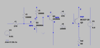
The circuit attached is used as an on/off switch to turn 60 ohms led on when v2 is below around 0.6V or below and to turn led 60 ohms off when v2 is above 0.6V. I have been trying for four months to do circuit analysis and to calculate hysteresis but I finally I admit I need help. Part of the problem is I am not sure where to start for circuit analysis and Q1 collector tied to Q2 base and resistor r5 also tied to Q3 collector is confusing me. Can someone please calculate hysteresis for the below circuit and go through the circuit analysis?
 

Attachments

  • circuit.png
    circuit.png
    32.2 KB · Views: 8

bertus

Moderator
Nov 8, 2019
3,836
Joined
Nov 8, 2019
Messages
3,836
Hello,

That circuit has been an intens discussion on AAC:

Bertus
 

hhsting

Jan 6, 2025
2
Joined
Jan 6, 2025
Messages
2
Hello,

That circuit has been an intens discussion on AAC:

Bertus
Not the calculation it is not shown. I know what circuit is and hysteresis is.
 

Harald Kapp

Moderator
Moderator
Nov 17, 2011
14,271
Joined
Nov 17, 2011
Messages
14,271
I am not sure where to start for circuit analysis
Obviously this circuit has two states: on and off.
Start with V2 = 0 V to calculate an initial steady state of the circuit. Hint: Q1 = off in this state.
From that starting point you can find the point at which V2 turns on Q1, putting the circuit in a second state.
From this second state you can in turn find the point at which V2 turns off Q1, putting the circuit in a second state. This voltage should be less than the voltage that turns on Q1. The difference between these two voltages is the hysteresis.
 
Top