Forward reverse switch HELP!

Zubzero

Mar 20, 2025
11
Joined
Mar 20, 2025
Messages
11
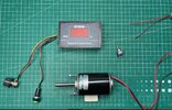
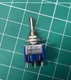
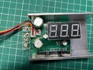
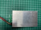
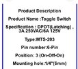
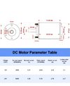
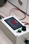
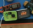
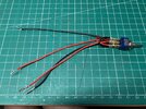
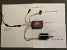
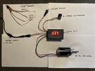
Hi,I’m new to the forum and electronics.i have a dc motor plus power supply and a motor control unit that can control the speed of the motor and turn it on and off see(photos)I want to add a forward/reverse switch to the set up(small blue switch in photos)can someone please advise me if I can do this to the current set up and where to connect the wires to do so.if you need any more information please ask.
 

Attachments

  • IMG_4823.jpeg
    IMG_4823.jpeg
    376.5 KB · Views: 6
  • IMG_4824.jpeg
    IMG_4824.jpeg
    335.3 KB · Views: 7
  • IMG_4825.jpeg
    IMG_4825.jpeg
    294.2 KB · Views: 5
  • IMG_4826.jpeg
    IMG_4826.jpeg
    314 KB · Views: 6

Alec_t

Jul 7, 2015
3,817
Joined
Jul 7, 2015
Messages
3,817
Welcome to maker.pro.
1) What are the rated full speed current and stall current of that motor?
2) I see no DC rating for the switch, so it may not be happy if motor stall current exceeds an Amp or two.
 

Minder

Apr 24, 2015
3,561
Joined
Apr 24, 2015
Messages
3,561
That is a DC brushed motor, by the look of it you would normally use a SW with centre-off as it is not good to go from one direction to another without stop. the motor that can do this without pause is a stepper motor.
 

Zubzero

Mar 20, 2025
11
Joined
Mar 20, 2025
Messages
11
Hi, thanks for your reply’s here is some(photos)for information on the motor and switch.have I got the wrong switch? If so what do you recommend.
 

Attachments

  • IMG_4828.jpeg
    IMG_4828.jpeg
    81.7 KB · Views: 5
  • IMG_4827.jpeg
    IMG_4827.jpeg
    73.7 KB · Views: 5

Zubzero

Mar 20, 2025
11
Joined
Mar 20, 2025
Messages
11
Just a mention I did connect the DPDT switch to the motor and power supply without the motor control unit and it worked fine,but then I tried to wire it in with the control unit and it did not work as it should.ive seen a couple of pictures online where people have added forward/reverse switches to the control units how is this done?thanks for your reply’s.
 

Zubzero

Mar 20, 2025
11
Joined
Mar 20, 2025
Messages
11
Here is two photos with the same speed control unit as I have but they have added forward/reverse switches.
 

Attachments

  • IMG_4829.jpeg
    IMG_4829.jpeg
    119.2 KB · Views: 3
  • IMG_4806.jpeg
    IMG_4806.jpeg
    47.8 KB · Views: 3

Minder

Apr 24, 2015
3,561
Joined
Apr 24, 2015
Messages
3,561
For reverse feature, The switch should have 6 terminals DPDT, (image IMG_ 4824.jpg)
The -/+ power goes to centre two the motor is fed from one end or the other, a connection is made from the remaining two bur crossed over,
see pic

1742568834794.png
 

Zubzero

Mar 20, 2025
11
Joined
Mar 20, 2025
Messages
11
Thanks minder,I have all ready done That see photo below.i also connected the wires from the dpdt switch to the motor and power supply when I powered it up it works fine,but if I add the speed controller unit to the set up the dpdt switch does not work as it should,if that makes sense.do I connect the dpdt switch wires to the speed controller unit in some way to get it to work properly?I just don’t know.thanks for you reply.
 

Attachments

  • IMG_4833.jpeg
    IMG_4833.jpeg
    426.9 KB · Views: 2

Minder

Apr 24, 2015
3,561
Joined
Apr 24, 2015
Messages
3,561
In all probability the switch would go after the speed controller
Or at least the pair of motor side leads
 

Alec_t

Jul 7, 2015
3,817
Joined
Jul 7, 2015
Messages
3,817
What is the current rating of the controller? If it is less than 3.1A then it is probably going into self-protect mode when it tries to start the motor (which has a 3.1A stall current rating).
 

Zubzero

Mar 20, 2025
11
Joined
Mar 20, 2025
Messages
11
This is the information of the speed controller hope this helps.
 

Attachments

  • IMG_4834.jpeg
    IMG_4834.jpeg
    132.5 KB · Views: 6

Alec_t

Jul 7, 2015
3,817
Joined
Jul 7, 2015
Messages
3,817
Those controller specs are fine for that motor, but the DC current rating of the switch is not specified and its AC current rating is marginal.
 

Delta Prime

Jul 29, 2020
2,989
Joined
Jul 29, 2020
Messages
2,989
Here is two photos with the same speed control unit as I have but they have added forward/reverse switches
looksto me like there are, photos of two separate speed controller units!
So I must believe you…independent of that we need to see your
Photos , your connections to the various modules you have purchased we need everything Make model of all modules and photos of how you connected them. It’s operator error, that means you, but that’s OK. The more eyes looking at your set up the better. We need photos of yourwork,where your connections are made because it should work you are the only Variable in this discussion.
Photo below is of your connections. I can’t see crap. Can you draw? You would probably have to do the same with the photos you take of your connections draw them out as well as best you can.
1742596948864.png
 
Last edited:

Zubzero

Mar 20, 2025
11
Joined
Mar 20, 2025
Messages
11
hope these photos help.the first photo shows the setup running,in the second photo where do I wire the dpdt switch too so I can have forward reverse.
 

Attachments

  • IMG_4838.jpeg
    IMG_4838.jpeg
    246.6 KB · Views: 8
  • IMG_4841.jpeg
    IMG_4841.jpeg
    260.3 KB · Views: 8

Zubzero

Mar 20, 2025
11
Joined
Mar 20, 2025
Messages
11
If you had the setup in the first photo and wanted to have a forward/reverse function how would you do that?would you use a different switch?if so what kind of switch.
 

Harald Kapp

Moderator
Moderator
Nov 17, 2011
14,282
Joined
Nov 17, 2011
Messages
14,282
The switch goes between controller and motor, like so:
1742801488573.png

You don't have to physically cut the wires as indicated. Simply unscrew from the controller's terminals.
 
Top