Power supply?

HarryA

Jan 22, 2017
90
Joined
Jan 22, 2017
Messages
90
Greetings from cold Pennsylvania.

I am working on a power supply that I took to be dual polarity
power supply with variable output.

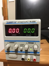
The power supply has three terminals: red for positive, black for negative, and
yellow for neutral (?).

But on setting the voltage for 10 volts you get 10 volts between the positive (red) and
negative (black) terminals. But you get 15+ volts ac between the positive or negative terminals
to the neutral (yellow) terminal. The yellow terminal and the power cord ground are the only
connections I can find to case/ground.

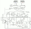
This is a DAZHENG PS303d. Photo and circuit schematic included.

I am thinking it looks like a duck but does not swim like a duck.
 

Attachments

  • photo.png
    photo.png
    594.5 KB · Views: 13
  • ps-305d-circuit.png
    ps-305d-circuit.png
    118 KB · Views: 16

bertus

Moderator
Nov 8, 2019
3,835
Joined
Nov 8, 2019
Messages
3,835
Hello,

Looking at the schematic, it is a single powersupply.
The connection of the yellow post is not in the schematic.
The two meters are for voltage and current.

Bertus
 

AnalogKid

Jun 10, 2015
3,045
Joined
Jun 10, 2015
Messages
3,045
The yellow terminal might be a chassis / earth ground. With everything disconnected and off, measure the resistance between the yellow terminal, some exposed chassis metal, and the GND pin on the line cord.

ak
 

HarryA

Jan 22, 2017
90
Joined
Jan 22, 2017
Messages
90
Both are connected to the case.

I would think if you had an op amp that required both positive and
negative power this power supply would not work because
the yellow terminal is not a "real" ground from a power supply
perspective?

Open circuit the voltage between the red and yellow terminals:
7.1 Vpp ac via scope and 2.13 V ac by meter. (60 Hz)

For loads less than 10k ohms it is very low.

At 10k ohms:
120 mv ac via scope and 23 mv ac by meter.

At 100k ohms:
700 mv ac via scope and 230 mV ac by meter.
 

AnalogKid

Jun 10, 2015
3,045
Joined
Jun 10, 2015
Messages
3,045
Per the schematic, the power supply circuit output is completely floating with respect to earth ground. That is, both terminals (black and red) are galvanically isolated from the device chassis and the mains earth ground. In some situations, it is desired for the supply's output to be referenced to earth, so a jumper terminal is brought out to the front panel for convenience.

Gold star for providing the schematic.

ak
 

HarryA

Jan 22, 2017
90
Joined
Jan 22, 2017
Messages
90
In the schematic on the far left note the three transformer
windings that supply voltage to the main circuit.

There are 9v, 12v, and 16volts. The two relays connecting the
windings to the bridge rectifier can supply voltages of:
12v, 21v, 28v, and 37v as required?

I gather the circuit switches the voltages as the user requests
more or less voltage output?

The relay drivers are in the schematic at the far right and at the upper part
of the larger diagram.
 

AnalogKid

Jun 10, 2015
3,045
Joined
Jun 10, 2015
Messages
3,045
There are 9v, 12v, and 16volts. The two relays connecting the
windings to the bridge rectifier can supply voltages of:
12v, 21v, 28v, and 37v as required?
Yes. This type of auto-ranging is used to reduce the heat in the pass transistors when supplying high currents at low voltages. Stepping down the voltage input to the regulator can reduce the heat by a lot, maybe 75% in some conditions depending on the auto-ranging circuit design.

ak
 

HarryA

Jan 22, 2017
90
Joined
Jan 22, 2017
Messages
90
Good points.

As the power supply itself has a split power supply off
the 19-19 volt windings one could "borrow" a few ma from
that for experiment. Adding three terminals at the back of the case.

The KBP210 bridge rectifier is rated 2.0 amperes and the
15v regulators (L7915/L7815) at 1.5 amperes.

The circuit board is through hole so it makes it much easier
to deal with.
 

davenn

Moderator
Sep 5, 2009
14,470
Joined
Sep 5, 2009
Messages
14,470
As the power supply itself has a split power supply off
the 19-19 volt windings one could "borrow" a few ma from
that for experiment. Adding three terminals at the back of the case.

probably good, but fuse each rail at the max of 0.5 - 0.8A to be safe

The KBP210 bridge rectifier is rated 2.0 amperes and the
15v regulators (L7915/L7815) at 1.5 amperes.

True, but that doesnt infer that the transformer winding is capable of an amp or more
So do as my first comment says :)

Dave
 

AnalogKid

Jun 10, 2015
3,045
Joined
Jun 10, 2015
Messages
3,045
As the power supply itself has a split power supply off
the 19-19 volt windings one could "borrow" a few ma from
that for experiment. Adding three terminals at the back of the case.
NOTE that the ground for the +/-15 internal supplies and the ground for the main output are n.o.t the same.

ak
 
Top