555 output question

FractalCat

May 11, 2021
5
Joined
May 11, 2021
Messages
5
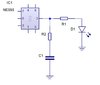
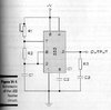
I have a schematic of the 555 IC where the output pin is connected to an LED and also to a resistor and capacitor and then to ground, which to me looks like an RC circuit or a low pass filter. The LED is not in series with the resistor and capacitor they have different connections. What's going on here? What is the purpose of the resistor and capacitor in this circuit?

Thanks

Fractal Cat
 

bertus

Moderator
Nov 8, 2019
3,837
Joined
Nov 8, 2019
Messages
3,837
Hello,

Could you post a schematic?
You can upload picture files upto 300 kB.

Bertus
 

FractalCat

May 11, 2021
5
Joined
May 11, 2021
Messages
5
Hello,

Here's the schematic. What are the resistor and capacitor for in this circuit?

Thanks

FC
 

Attachments

  • 555.jpg
    555.jpg
    27.3 KB · Views: 18

Audioguru

Sep 24, 2016
3,656
Joined
Sep 24, 2016
Messages
3,656
The maximum allowed output current of an ordinary old 555 is 200mA that will quickly burn out an ordinary LED that has a maximum allowed continuous current of 30mA. Therefore the LED needs a series current-limiting resistor.
The 555 might be a modern Cmos LMC555, TLC555 or ICM7555 that has much less output current.

EDIT: Your ordinary old NE555 has a resistor R1 to limit current to the LED.
I do not know why there is R2 and C1 at the output of the 555 to ground.
 

FractalCat

May 11, 2021
5
Joined
May 11, 2021
Messages
5
I'm aware of this but it doesn't explain the purpose of the capacitor in series with the other resistor.
 

Harald Kapp

Moderator
Moderator
Nov 17, 2011
14,272
Joined
Nov 17, 2011
Messages
14,272
R2+C1 make no sense. Where did you get that schematic from? An explanation may be found on that website.
 

FractalCat

May 11, 2021
5
Joined
May 11, 2021
Messages
5
This schematic was taken from Electronics for Dummies as a hobbyist project. So what are the series resistor and capacitor doing
in this circuit?
 

Attachments

  • 555Capture_fast_flasher_circuit.JPG
    555Capture_fast_flasher_circuit.JPG
    29.1 KB · Views: 11

bertus

Moderator
Nov 8, 2019
3,837
Joined
Nov 8, 2019
Messages
3,837
Hello,

Strange, the book I got shows a different circuit:
dummies 555 timer.png
There is no resistor / capacitor combination on the output.

Bertus
 

FractalCat

May 11, 2021
5
Joined
May 11, 2021
Messages
5
Ahh, now I understand. This makes more sense. So the book has a mistake. Well, I've seen that before with
other texts.

Thanks Bertus
 

AnalogKid

Jun 10, 2015
3,045
Joined
Jun 10, 2015
Messages
3,045
In the first image, C3 is supposed to be the LED. The clue is the resistance value of R3, which is correct for a normal small LED and VCC values up to +12 V.

ak
 
Top