Geneva XL trouble with PSU

Dynabogg

May 21, 2025
1
Joined
May 21, 2025
Messages
1
Hi everyone

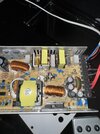
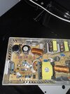
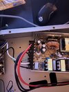
I’m not sure this is the right forum for this but I saw another post about a similar speaker and thought I’d give it a try. I’m new to electronics but I’m trying to figure out what’s wrong with the PSU in the speaker. I have figured out that there is something wrong with the PSU since it’s varying between 19-21 VDC when it should output 48 V. I used my thermal camera and could see that 2 resistors almost got up to 60 degrees celsius but I’m not sure how to troubleshoot further
 

Attachments

  • IMG_3528.jpeg
    IMG_3528.jpeg
    316.5 KB · Views: 7
  • IMG_3527.jpeg
    IMG_3527.jpeg
    310.7 KB · Views: 6
  • IMG_3526.jpeg
    IMG_3526.jpeg
    254.2 KB · Views: 6

Harald Kapp

Moderator
Moderator
Nov 17, 2011
14,281
Joined
Nov 17, 2011
Messages
14,281
I have figured out that there is something wrong with the PSU since it’s varying between 19-21 VDC when it should output 48 V.
The fault is not necessarily with the PSU. A low output voltage in conjunction with the hot resistors may also point to an overload of the PSU by a fault in the load aka amplifier section. Depending on the design of the PSU it may not turn off in case of overload but reduce the output voltage to reduce the power dissipation.
Can you separate the amplifier from the PSU and measure the PSU's output without load current? Also measure the temperature of the resistors without load current. Additionally you may connect an ammeter between the PSU and the amplifier and measure the load current.
 

73's de Edd

Aug 21, 2015
3,730
Joined
Aug 21, 2015
Messages
3,730
Sir Dynabogg . . . . .
Why for you no answer Sir Kapp's post ?
also . . . . . .WHATS DA MATTAH WITH YOU ? . . . . . . . in your not marking those two hot resistors so that we know what they are and are located ?
I'm Having to pull out and use my SUPER-DUPER 48 inch Swarovsky CRYSTAL SEER BALL and therein envison those units as being in the output circuitry of the switch modes transformers secondary.
You will see them as the two blue-grey metal film 1 or 2 watt resistors,that are vertically mounted on the P.S. circuit board, ALL of the other resistors that I see are mounted against the board and are being lesser rated CARBON film units.
Referring to their relevant photo . . .the very 1st one . . . . . whch has a SET marker in far right bottom corner and 2 heavy red and black wires outputting from a terminal strip.
Inwards, to the left, from that strip is a cluster of inductive and multiple electrolytic capacitor DC filtering elements. You will find those 2 mentioned
resistors within that cluster.
There are 3 critical E-caps in that c,luster that provide filtering for that branch of your supply..
Now, if an E-cap has decreased APPRECIABLY in its effective capacitive capability, the resistor that it feeds out into. will overheat , due to the next following E-cap, trying to compensate for the earlier dud E-capacitor.
Upon viewing, one does not see any FLAGRANTLY . . . . . domed-split-burst aluminum top caps X-scorings on those three caps, so a definitive testing or outright replacement with 3 like 130 degree temp rated like valuedunits might be required.
I stop now . . . . . . awaiting your response.
HINT . . . . . .most other L units in the past, have had bad E-caps further on down this same supply line at the AUDIO POWER OUT MODULE PANEL.


73's de Edd . . . . . . . .

( HOT DAMN ? I must have a DAMN PUTIN-SKI originated RUSSKIE spy bot on my tail, because it wanted to spell correct my Swarovsky crystal to Khabarovsk)
 
Last edited:
Top