Hello,
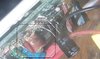
my central heating would not start / stop every time the transmitter thermostat would issue a start / stop command, but only some of the time. Took the receiver apart, found the film cap (yellow) next to the output relay to be off by a big factor (200 nF measured / 560 nF nominal) and proceeded to replacing it.
Put everything back together and... the receiver would not start at all. Switched back to its faulty yellow cap, still nothing. Of course, I don't know how I have managed to break it that badly. Measured its input at 227 V and its on-off switch to be still closing/opening the circuit.
I have noticed this gooey area in the middle of the PCB, feels wax-like and pretty dry; I don't think I have caused any component to spill that goo out but I would like a second opinion. A similar (if not same) substance is present in the two lower left corners - attached to that red wire and even inside the on-off switch. Could that be causing any issues ?
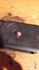
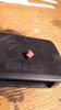
 . Let me grab a photo of it from its side.