Hegner Scroll Saw - Motor speed control issue

P.Evans

Nov 13, 2024
9
Joined
Nov 13, 2024
Messages
9
Hello,
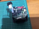
I’ve been given a Hegner scroll saw, which runs but when I turn the speed controller there is no change in speed.
I‘m not very experienced at fault finding at component level and this why I’m asking for your help.
The saw is powered by 230V AC and I’m little apprehensive fault finding while the board is live.
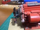
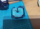
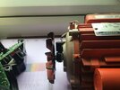
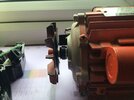
On the end of the motor shaft next to the fan is magnet and on the motor casing is a sensor (see attached photo), I think this is for sensing motor rotation. Not sure how to test this, I have tried turning the shaft and checking for resistance and voltage but I get no change in meter reading.
I’ve tried looking for a wiring diagram on the net but can’t find one and I think Hegner want you to buy a new unit, dread to think how much that would cost.
My friend who owned the saw previously bought another speed controller but thus didn’t cure the issue. The replacement controller is a later V.2 board.
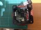
In my naivety I changed all the main components on the original board hoping I could fix it by substituting components without really understanding the components or circuit.
I realise this is difficult to diagnose over the web but if there was a member who lived in the Midlands (I live south of Birmingham) and offer me guidance I would be extremely grateful.
Many thanks in advance,
Paul Evans
 

Attachments

  • IMG_1366.jpeg
    IMG_1366.jpeg
    306.8 KB · Views: 17
  • IMG_1368.jpeg
    IMG_1368.jpeg
    329.2 KB · Views: 17
  • IMG_1369.jpeg
    IMG_1369.jpeg
    303.4 KB · Views: 17

Bluejets

Oct 5, 2014
7,374
Joined
Oct 5, 2014
Messages
7,374
What is the model number?

There are fixed and variable speed models and your motor nameplate only says 1400 rpm.
Not 400/1400 as in the variable speed type.

M2039 fixed
M2040 variable
 

P.Evans

Nov 13, 2024
9
Joined
Nov 13, 2024
Messages
9
Hello Bluejets and thank you for your reply,

My scroll saw is:
Hegner Multicut 2S Serial No: 65377/94.

I’ll check with Hegner to see if I have the correct motor.

Thanks,

Paul
 

P.Evans

Nov 13, 2024
9
Joined
Nov 13, 2024
Messages
9
Hello Bluejets,
Hegner UK have replied to my email, it’ll take them till next week to give me an answer.
I’ll keep you informed,
Paul
 

73's de Edd

Aug 21, 2015
3,730
Joined
Aug 21, 2015
Messages
3,730
Sir Paul . . . . . .


W e l l l l l l l l l l . . . . . .
if that controller photo is being of the original motor speed controller, it seems to have all of the required components in it.
The motor spec plate of 1400 is probably the max speed of the motor and its being about a 1/4+ . . horsepower capacity.
One sees a lightly heat sinked power SCR or Triac at top of that circuit board..
At bottom is an 18 pin I.C. that suggests of a microcontroller/processor smart chip or custom application unit.
The small frontal PIHER type black pot is probably used to trim in the lower speed.
Per chance is there a low / high speed switch used ?
but your . . . .
but when I turn the speed controller
suggests, only a variable pot / control.
Possibly, high speed being with this controller bypassed and low., is with controller in line .
Any chance that this unit was of 1985-87'ish age vintage, as some visible part date code markings suggest ?

73's de Edd . . . . .
 

P.Evans

Nov 13, 2024
9
Joined
Nov 13, 2024
Messages
9
Hello 73’s de Edd,
Many thanks for your reply.
I believe the Hegner saw was built in 1994, as the serial no. is: 65377/94.
Regards,
Paul
What is the model number?

There are fixed and variable speed models and your motor nameplate only says 1400 rpm.
Not 400/1400 as in the variable speed type.

M2039 fixed
M2040 variable
Hello Bluejets,
Hegner via the UK agent have got back to me today with this message:

I forwarded your picture over to Hegner and they have confirmed the following:


“this should be a motor with variable speed control”


I hope this helps.

My friend who gave me the saw, said he thought it was the original motor.

Any thoughts?

Paul
 

73's de Edd

Aug 21, 2015
3,730
Joined
Aug 21, 2015
Messages
3,730
Sir Paul . . . . .

Any thoughts?
YEP ! shore do . . . . .

The power control aspect of that controller is being that heat sinked Triac or SCR.
If mounting hardware is not obscuring parts ID of that unit, pass it on to us . . . . . or tear on down until being able to read.
Speed control is being dependent on either variable frequency or variable pulse width bursts of gate turn on wavelets activating the gate of that
SCR / TRIAC.
So o o o o o o o o o o o its anode / cathode . . . . . in the case of a SCR or its MT1-MT2 terminals . . . . . in the case of a Triac . . . . .internal semiconductor junctions must have failed and are now shorted together.
Thereby, you are having a motor running at full speed and no capability of proportional gate control with no gate control capability.

If having already changed other parts . . . . . . . you are undoubtedly adept at soldering . . . . so un solder the three leads associated with that device and pull it.
You will then need referencing to a data sheet of that part unless its pcb had its terminal connections silk screened on.
With part in hand expect two terminals . . . . .or sometimes . . . . all three terminals to be shorted together . . . . . when metered with a low ohms test.
Inform us of the devices part number and I will show you how to ascertain gate drive presence, as is selected by that center board variable speed control pot that faces to the other side of the board with its knob.
Thaaaaaaaassssssssit . . . . .


73's de Edd . . . . .


bathroom-knocker.gif
 

Bluejets

Oct 5, 2014
7,374
Joined
Oct 5, 2014
Messages
7,374
Sir Paul . . . . .

Any thoughts?
YEP ! shore do . . . . .

The power control aspect of that controller is being that heat sinked Triac or SCR.
If mounting hardware is not obscuring parts ID of that unit, pass it on to us . . . . . or tear on down until being able to read.
Speed control is being dependent on either variable frequency or variable pulse width bursts of gate turn on wavelets activating the gate of that
SCR / TRIAC.
So o o o o o o o o o o o its anode / cathode . . . . . in the case of a SCR or its MT1-MT2 terminals . . . . . in the case of a Triac . . . . .internal semiconductor junctions must have failed and are now shorted together.
Thereby, you are having a motor running at full speed and no capability of proportional gate control with no gate control capability.

If having already changed other parts . . . . . . . you are undoubtedly adept at soldering . . . . so un solder the three leads associated with that device and pull it.
You will then need referencing to a data sheet of that part unless its pcb had its terminal connections silk screened on.
With part in hand expect two terminals . . . . .or sometimes . . . . all three terminals to be shorted together . . . . . when metered with a low ohms test.
Inform us of the devices part number and I will show you how to ascertain gate drive presence, as is selected by that center board variable speed control pot that faces to the other side of the board with its knob.
Thaaaaaaaassssssssit . . . . .


73's de Edd . . . . .


bathroom-knocker.gif
Agree.....however, wouldn't be the first time someone has fiddled and stuffed a speed control in an old motor for whatever reason.
That is what made me suspicious.
Strange reply from manufacturer though " that this should be....." although previous owner also "thought it should be original............"
Carry on ....... can only hope pcb side is not "potted".
 

P.Evans

Nov 13, 2024
9
Joined
Nov 13, 2024
Messages
9
Sir Paul . . . . .

Any thoughts?
YEP ! shore do . . . . .

The power control aspect of that controller is being that heat sinked Triac or SCR.
If mounting hardware is not obscuring parts ID of that unit, pass it on to us . . . . . or tear on down until being able to read.
Speed control is being dependent on either variable frequency or variable pulse width bursts of gate turn on wavelets activating the gate of that
SCR / TRIAC.
So o o o o o o o o o o o its anode / cathode . . . . . in the case of a SCR or its MT1-MT2 terminals . . . . . in the case of a Triac . . . . .internal semiconductor junctions must have failed and are now shorted together.
Thereby, you are having a motor running at full speed and no capability of proportional gate control with no gate control capability.

If having already changed other parts . . . . . . . you are undoubtedly adept at soldering . . . . so un solder the three leads associated with that device and pull it.
You will then need referencing to a data sheet of that part unless its pcb had its terminal connections silk screened on.
With part in hand expect two terminals . . . . .or sometimes . . . . all three terminals to be shorted together . . . . . when metered with a low ohms test.
Inform us of the devices part number and I will show you how to ascertain gate drive presence, as is selected by that center board variable speed control pot that faces to the other side of the board with its knob.
Thaaaaaaaassssssssit . . . . .


73's de Edd . . . . .


bathroom-knocker.gif
Thank you for your reply, I’ll do as you suggest and get back to you. I’ve added a couple more photos of the circuit board. Thanks again.
 

Attachments

  • IMG_1417.jpeg
    IMG_1417.jpeg
    389.3 KB · Views: 8
  • IMG_1416.jpeg
    IMG_1416.jpeg
    333.8 KB · Views: 8

P.Evans

Nov 13, 2024
9
Joined
Nov 13, 2024
Messages
9
Hello,
Many apologies for the length of time in replying but now Christmas is behind us I will hopefully have more time.
Thanks for the replies but before I start desoldering components could someone tell me how to measure or check the motor spindle sensor is working correctly. Please see attached photos. The reason I need to check this is because both motor speed controllers have the same issue (motor running at high speed), so I would like to eliminate the motor sensor first of all. I’ve tried spinning the motor and measuring the output using Volts or Ohms settings on the DVM but get no change in reading. I do hope I’m making an elementary error here

Please advise

Many thanks,

Paul
 

Attachments

  • IMG_1531.jpeg
    IMG_1531.jpeg
    229.9 KB · Views: 8
  • IMG_1530.jpeg
    IMG_1530.jpeg
    226.8 KB · Views: 8

Minder

Apr 24, 2015
3,561
Joined
Apr 24, 2015
Messages
3,561
The two wire connection indicates it could be a optical unit, or even magnetic sensor, either way, the signal would likely be just 0v to whatever the sensor supply is, i.e. , LV DC .
You may have to turn it really slow to see the square wave out put.
 

P.Evans

Nov 13, 2024
9
Joined
Nov 13, 2024
Messages
9
The two wire connection indicates it could be a optical unit, or even magnetic sensor, either way, the signal would likely be just 0v to whatever the sensor supply is, i.e. , LV DC .
You may have to turn it really slow to see the square wave out put.
Many thanks for the reply Minder. I’m guessing the only way to see a square wave form is with an oscilloscope?
 

Minder

Apr 24, 2015
3,561
Joined
Apr 24, 2015
Messages
3,561
Many thanks for the reply Minder. I’m guessing the only way to see a square wave form is with an oscilloscope?
It is likely that it is coarse enough to see with a meter if turned VERY slowly !
 

P.Evans

Nov 13, 2024
9
Joined
Nov 13, 2024
Messages
9
BTW is there any manuf. markings on the sensor?
Hello,
I’ve tried connecting the sensor to my DVM but get no change in reading, on the mV scale there is a 0.1mV reading but I think that’s just noise. I get a bigger reading if I move the test leads. Nothing on the V (ac or dc), or when set to Ohms
There are no markings on the sensor.
Maybe an analogue meter would better for this test?
Thanks for your help.
 

Delta Prime

Jul 29, 2020
2,987
Joined
Jul 29, 2020
Messages
2,987
Nothing on the V (ac or dc), or when set to Ohms
I would Ohmmit that last part.
when you set your multimeter to ohms (resistance measurement) & your probes to an AC source, the internal voltage source used for resistance measurements can interact dangerously with the live AC voltage, potentially causing a circuit overload or blowing the multimeter's fuse.
 

P.Evans

Nov 13, 2024
9
Joined
Nov 13, 2024
Messages
9
I would Ohmmit that last part.
when you set your multimeter to ohms (resistance measurement) & your probes to an AC source, the internal voltage source used for resistance measurements can interact dangerously with the live AC voltage, potentially causing a circuit overload or blowing the multimeter's fuse.
Hello,
Thanks for the reply and warning. I’m only testing the speed sensor as suggested by Delta Prime and turning the motor by hand, not powered up.
 

Minder

Apr 24, 2015
3,561
Joined
Apr 24, 2015
Messages
3,561
If no power on then you would only see a result if it was a passive device such as the magnetic version, and then it would likely be a contact closure, otherwise a optical type for e.g. you would see no difference.
 
Top