I am using 10 Peltier devices connected in parallel. Each device is rated 12 VDC, 15 Amps. My concern is with initial power up. In prior experiments, at the instant of power on, the Peltier device appears as almost a dead short. Once the diode junctions begin to heat up, the device will limit current, usually well below the device's rated maximum current. It is my assumption that if all heat generated could be drawn off the device, then the device will be in a state to allow maximum current flow or even over maximum flow resulting in destruction of the device. In my current experiment, I will be powering the 10 devices with a 24 VDC to 12 VDC, 40 A voltage converter. At the instant of power on, I fear the devices will appear as a short circuit and that the high current demand will fry my converter. Somewhere in my parts heap, I had 4 high power (maybe 1 kW) resisters. I recall their resistive value to be around 0.392 ohms. I could put one in series with my circuit and that would alleviate my worries. I can't find the resister right now, though. Two 12 V lead/acid glass mat batteries, each rated 100 AH, in series, will be used as the power supply. How do I limit my current flow at initial power on?
You are using an out of date browser. It may not display this or other websites correctly.
You should upgrade or use an alternative browser.
You should upgrade or use an alternative browser.
High current, 40 A to 100 A, current limiting devices other than a resistor
- Thread starter HANKMARS
- Start date
Scroll to continue with content
What's the problem with using one or more of those power resistors?How do I limit my current flow at initial power on?
Why does your title say "other than a resistor"?
Last edited:
- Joined
- Nov 17, 2011
- Messages
- 14,097
You're looking for an inrush current limiter.
A fixed resistor will dissipate power during "normal" operation.
An NTC will provide initial resistance which drops during operation to reduce losses, but losses there are.
You could insert an electronic current limiter using e.g. bipolar transistors or MOSFETs
Alternatively turn on the Peltiers sequentially one after the other.
Martaine2005
- May 12, 2015
- 5,152
- Joined
- May 12, 2015
- Messages
- 5,152
- Joined
- Nov 17, 2011
- Messages
- 14,097
Plus, possibly, a voltage limiter (VDR, suppressor diode or similar) to suppress the high voltage spike from the coil when the power is turned off hard via a switch.Over simplification but classic inductor/choke
HANKMARS replied to a thread you are watching at Electronics Forums.
High current, 40 A to 100 A, current limiting devices other than a resistor
danadak said:
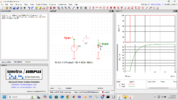
Over simplification but classic inductor/choke :
View attachment 66144
You can online get spice models to do a real sim as TEC is not a simple device due to thermal mass
and other time dependent repsonse it has.
I believe a series inductor may be the way to go. If as in the case where I desire to do testing with batteries that will deliver high current, an inductor of the proper value should work just fine. What I can add to the circuit is a make before break switch which will eliminate the inductor from the circuit. That would provide full power to the circuit after start up and avoid an over current demand on the converter during start up. There is a problem, with testing with batteries, that I failed to mention. The batteries that I would be using in testing will be able to deliver current that exceeds the Peltier ratings. As I understand a Peltier device, it is merely an array of p/n junctions. Therefore, if I do not limit the current, the result would be the same as if I put a 15 amp diode between the posts of a hundred amp battery and expected the diode to limit the current, which it won't, until it burns open. Also, I do not believe my 24 V to 12 V converter will limit current flow to its 40 amp rating. My guess is that the converter will try to match whatever current the circuit calls for and the converter will self-destruct. My initial design has the output of 4 PV panels, each 250 watts, hooked in parallel, directly hooked to the input of the 24 to 12V converter. The converter has an input V range of 19-35 volts. PV panel, no load voltage is 36 volts. Short circuit amperage is around 8 amps. My charge controllers have read as high as 39 amps at their inputs, which I do not fully understand but run with anyway. Voltage input to charge controllers consistantly reads right around 13,1 volts. I'm still learning about PV actions.
**************************************************************************************************
Some interesting I-V info here - https://www.labcenter.com/blog/sim-peltier-models/
A handbook - https://www.dropbox.com/scl/fi/jfbo...ey=mtf9bz4skp9vmmukmowpkk01m&st=6iposdt0&dl=0
Regards, Dana.
Last edited by a moderator:
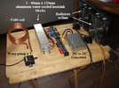
The Poteous site is a good read. CRC of course contains enough data for a 4 year college course. Do you have to have a membership or pay a fee to get CRC data? It seems that the hard copy book was around 500 dollars, about 30 years ago. I will keep both links. Thanks. Current state of test fixture.HANKMARS replied to a thread you are watching at Electronics Forums.
High current, 40 A to 100 A, current limiting devices other than a resistor
danadak said:
Over simplification but classic inductor/choke :
View attachment 66144
You can online get spice models to do a real sim as TEC is not a simple device due to thermal mass
and other time dependent repsonse it has.
I believe a series inductor may be the way to go. If as in the case where I desire to do testing with batteries that will deliver high current, an inductor of the proper value should work just fine. What I can add to the circuit is a make before break switch which will eliminate the inductor from the circuit. That would provide full power to the circuit after start up and avoid an over current demand on the converter during start up. There is a problem, with testing with batteries, that I failed to mention. The batteries that I would be using in testing will be able to deliver current that exceeds the Peltier ratings. As I understand a Peltier device, it is merely an array of p/n junctions. Therefore, if I do not limit the current, the result would be the same as if I put a 15 amp diode between the posts of a hundred amp battery and expected the diode to limit the current, which it won't, until it burns open. Also, I do not believe my 24 V to 12 V converter will limit current flow to its 40 amp rating. My guess is that the converter will try to match whatever current the circuit calls for and the converter will self-destruct. My initial design has the output of 4 PV panels, each 250 watts, hooked in parallel, directly hooked to the input of the 24 to 12V converter. The converter has an input V range of 19-35 volts. PV panel, no load voltage is 36 volts. Short circuit amperage is around 8 amps. My charge controllers have read as high as 39 amps at their inputs, which I do not fully understand but run with anyway. Voltage input to charge controllers consistantly reads right around 13,1 volts. I'm still learning about PV actions.
**************************************************************************************************
Some interesting I-V info here - https://www.labcenter.com/blog/sim-peltier-models/
A handbook - https://www.dropbox.com/scl/fi/jfbo...ey=mtf9bz4skp9vmmukmowpkk01m&st=6iposdt0&dl=0
Regards, Dana.
Attachments
poor mystic
- Apr 8, 2011
- 1,075
- Joined
- Apr 8, 2011
- Messages
- 1,075
Some arrangement of tungsten filament light bulbs might do the trick. One of these 200W 24V tungsten lamps in series with each Peltier module would be pretty safe. https://www.amazon.com/OSRAM-200W-MR16-Tungsten-Halogen/dp/B002DQVTIQ
Last edited:
Similar threads
- Replies
- 3
- Views
- 1K
- Replies
- 7
- Views
- 2K
- Replies
- 9
- Views
- 1K

