Miguel Lopez
- Jan 25, 2012
- 255
- Joined
- Jan 25, 2012
- Messages
- 255
Hello everybody
A couple of years ago, I began to build an oscilloscope from scratch. I had a Soviet C1-94, but the CRT failed, as well as several parts of the circuit that I had to repair from time to time. Finally the C1-94 got out of service and i wasn't able to fix it, mainly due to the CRT dying.
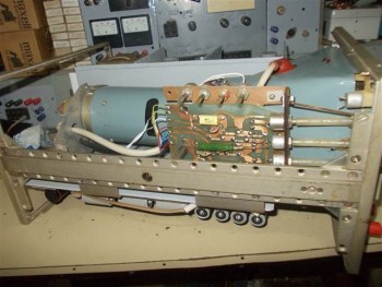
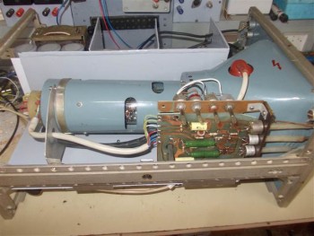
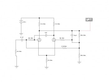
As by the time I was interested on vacuum electronics, and I had build my first valve amplifier, I thought that it would be a good idea to try to build my own valve-based oscilloscope. I used a cabinet from an old Soviet C1-99 scope that never worked. After weeks of study and trial and error test, I decided to used the circuit of the Telequipment S51 for the Y amplifier; and the circuit from the Telequipment Serviscope Minor for the X sweep generator.
This decision was in part due to their simplicity and in part due to the availability of components. I used the point-to-point technic to solder the components. For the EHT, first I used a high frequency multiplier, but this induced a lot on noise on the trace, so I opted to use a mains transformer with a high voltage winding and a bridge rectifier.The CRT was a Soviet 17LOI2 (100x120mm)
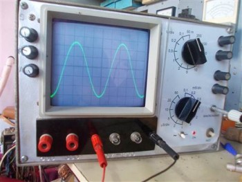
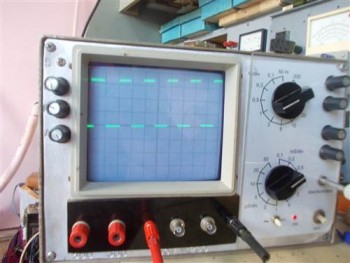
I built the scope after almost two years of work. Of course, I just worked on it from time to time, but still it was a great amount of working hours that I dedicated to this scope. It finally worked well, at least for my needs. (Up to 50kHz and up to 200V)
Well, once that scope was finished, it worked OK for a couple of months (+/-). I was in the glory. Then some day, it smoked and smelled burnt varnish. I checked it out and I found the EHT transformer was burnt. As to wind this transformer was very hard and time consuming (about 22000 turns + 5500turns) I decided that it was not a good idea to wind it again and expect for it to get burnt again.....well, I don't like to be a Sisyphus.
So the purpose of this thread is to share with my Odissey refurbishing my own oscilloscope. As now I have some background on vacuum electronics, this Version 2.0 of my scope, did not last too much, as it was the case with Version 1.0.
I decided to use another variant and I thought on the voltage multiplier that I had used at the beginning. As this voltage multiplier injected noise to the scope signal (it used the same HT PSU as the whole circuit), this time I need a diferent PSU. To avoid even to use the same power transformer, I rectified the mains directly and supplied the heaters of an ECL82 directly from mains using a capacitor in series.
The ECL82 triode was the oscillator and the pentode was the power output for the ferrite transformer. This circuit worked fine but it injected noise to the signal too. So, I thought that I had to obtain the EHT without oscillators, but without EHT transformer too. So I bet on for a 60Hz voltage multiplier.
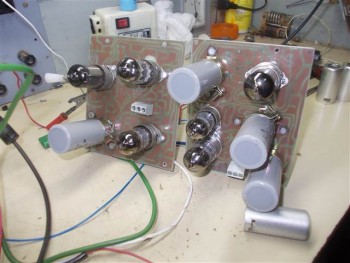
As building a 4kV multiplier from 60Hz required (for me) a big amount of components, I decided to use PCB to build these multipliers. Then, as at this point I had "betrayed" the Gods of point-to-point layout, I decided to betray at a bigger degree, so this time I used PCB for everything. Here some of the changes that I did:
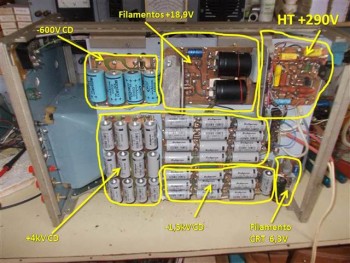
1.-) Generation of EHT is throught 60Hz voltage multiplier. Using 1N4007 diodes and 10uF/450V caps, supplied from a 120V winding in the mains transformer. +4kV, -1,5kV and -600V are now generated with these multipliers.
2.-) PCB for everything.
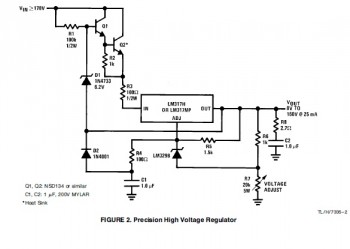
3.) All supplies are regulated (except those for EHT).
4.) According to above mentioned:
- HT regulated at 290V-
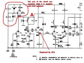
- HT2 for input stage, regulated at 150V-
- Heaters: regulated at 18,9V CD (three valves in series on each section of the circuit. Series supply to decrease the total current.
- Heaters supply elevated about 35V- from -HT
- CRT heater: Regulated at 6,3V-.
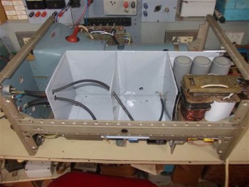
- To further noise reduction, the X and Y circuits are shielded from each other, with a new steel made chassis.
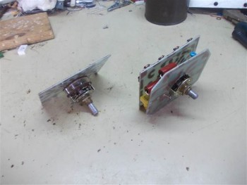
- Ranges sellector are now attached to a PCB with the required component, to avoid the use of wiring and so reducing possibility to induced noise.
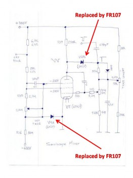
- Vacuum diodes from the sweep generator are now replaced by FR107 S-S diodes. (this is a betrayal to the Gods of Vacuum Electronics too, I'm a heretic)
- The circuitry for CRT supply is also mounted on a PCB and all required potentiometers for adjustment of CRT characteristics are now directly wired to the PCB.
In general, the circuits for X and Y amplifier are the same as in Version 1.0, but this time they are mounted on PCB. Now I will be sharing some pictures of the new version.
A couple of years ago, I began to build an oscilloscope from scratch. I had a Soviet C1-94, but the CRT failed, as well as several parts of the circuit that I had to repair from time to time. Finally the C1-94 got out of service and i wasn't able to fix it, mainly due to the CRT dying.
As by the time I was interested on vacuum electronics, and I had build my first valve amplifier, I thought that it would be a good idea to try to build my own valve-based oscilloscope. I used a cabinet from an old Soviet C1-99 scope that never worked. After weeks of study and trial and error test, I decided to used the circuit of the Telequipment S51 for the Y amplifier; and the circuit from the Telequipment Serviscope Minor for the X sweep generator.
This decision was in part due to their simplicity and in part due to the availability of components. I used the point-to-point technic to solder the components. For the EHT, first I used a high frequency multiplier, but this induced a lot on noise on the trace, so I opted to use a mains transformer with a high voltage winding and a bridge rectifier.The CRT was a Soviet 17LOI2 (100x120mm)
I built the scope after almost two years of work. Of course, I just worked on it from time to time, but still it was a great amount of working hours that I dedicated to this scope. It finally worked well, at least for my needs. (Up to 50kHz and up to 200V)
Well, once that scope was finished, it worked OK for a couple of months (+/-). I was in the glory. Then some day, it smoked and smelled burnt varnish. I checked it out and I found the EHT transformer was burnt. As to wind this transformer was very hard and time consuming (about 22000 turns + 5500turns) I decided that it was not a good idea to wind it again and expect for it to get burnt again.....well, I don't like to be a Sisyphus.
So the purpose of this thread is to share with my Odissey refurbishing my own oscilloscope. As now I have some background on vacuum electronics, this Version 2.0 of my scope, did not last too much, as it was the case with Version 1.0.
I decided to use another variant and I thought on the voltage multiplier that I had used at the beginning. As this voltage multiplier injected noise to the scope signal (it used the same HT PSU as the whole circuit), this time I need a diferent PSU. To avoid even to use the same power transformer, I rectified the mains directly and supplied the heaters of an ECL82 directly from mains using a capacitor in series.
The ECL82 triode was the oscillator and the pentode was the power output for the ferrite transformer. This circuit worked fine but it injected noise to the signal too. So, I thought that I had to obtain the EHT without oscillators, but without EHT transformer too. So I bet on for a 60Hz voltage multiplier.
As building a 4kV multiplier from 60Hz required (for me) a big amount of components, I decided to use PCB to build these multipliers. Then, as at this point I had "betrayed" the Gods of point-to-point layout, I decided to betray at a bigger degree, so this time I used PCB for everything. Here some of the changes that I did:
1.-) Generation of EHT is throught 60Hz voltage multiplier. Using 1N4007 diodes and 10uF/450V caps, supplied from a 120V winding in the mains transformer. +4kV, -1,5kV and -600V are now generated with these multipliers.
2.-) PCB for everything.
3.) All supplies are regulated (except those for EHT).
4.) According to above mentioned:
- HT regulated at 290V-
- HT2 for input stage, regulated at 150V-
- Heaters: regulated at 18,9V CD (three valves in series on each section of the circuit. Series supply to decrease the total current.
- Heaters supply elevated about 35V- from -HT
- CRT heater: Regulated at 6,3V-.
- To further noise reduction, the X and Y circuits are shielded from each other, with a new steel made chassis.
- Ranges sellector are now attached to a PCB with the required component, to avoid the use of wiring and so reducing possibility to induced noise.
- Vacuum diodes from the sweep generator are now replaced by FR107 S-S diodes. (this is a betrayal to the Gods of Vacuum Electronics too, I'm a heretic)
- The circuitry for CRT supply is also mounted on a PCB and all required potentiometers for adjustment of CRT characteristics are now directly wired to the PCB.
In general, the circuits for X and Y amplifier are the same as in Version 1.0, but this time they are mounted on PCB. Now I will be sharing some pictures of the new version.


")