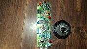
With proper volts present, one of 2 neons glows depending on polarity of auto engine spark .
I can only see
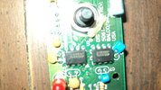
one neon on the board (Rear side)....Which I Imagine would be reference to any spark signal.
there are 3
LED's which I imagine you are referring to when you say "neon"
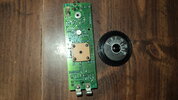
Polarity of the spark does not come in to the equation as it is always the same.
Polarity of the incoming power would I imagine be protected with a diode in which case if correct, LED adjacent to the switch would (I imagine) come on.
All three IC'c appear to be the same (dual comparator) so if you are familiar with the use of a multimeter, you should be able to trace incoming power through the board to each of these IC's at least.
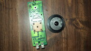
You should also get some variable voltage output on the centre pin of the pot and ground as you turn the knob one way or the other.
Taking care not to short anything while doing so.
That at least should be a starting point.
A description of what the meter actually does would also be of some assistance.
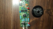
Normally one thing to check in aged-electronics such as this would be the condition of all electrolytic capacitors.
To achieve this, a decent capacitor/ component tester would be required with at least one leg of each device removed from the pcb.