LED Signal Dummy load

CDRIVE

Hauling 10' pipe on a Trek Shift3
May 8, 2012
4,960
Joined
May 8, 2012
Messages
4,960
lxlramlxl, I suspect that your requirements are far simpler than we tend to (sometimes) make things. If all you're desirous of doing is activating a current controlled relay then all you need is a power resistor like this. This 400Ω resistor will pull 300mA @ 120V and is rated at 50Watts.
s-l1600.jpg

Ebay lists quite a large selection of various resistance and wattage values.

Please tell us if your field tests require the return of any data. In other words since the dummy load will (as you say) tap into the existing circuit via Alligator Clips do you require an indicator that the relay contacts have closed?

It would help greatly if you could supply us with the resistance of the CCR. This way we can calculate the required value of the dummy load in series with it. An approximation of the input voltage isn't sufficient though. Is it in fact 120VAC?

Chris
 

CDRIVE

Hauling 10' pipe on a Trek Shift3
May 8, 2012
4,960
Joined
May 8, 2012
Messages
4,960
I didn't want to chance that you'd miss this, so I didn't want to edit my last post.

If you can post the specs of the ECR it would be a great help. If you can't find that then a manufacturer's Model/Part Number would probably suffice. Odds are there's an on-line datasheet available.

Chris
 

lxlramlxl

Jul 5, 2016
28
Joined
Jul 5, 2016
Messages
28
Yeah, a 40 watt glass light bulb is not what I want to stuff into my go-to bag. So LED it is. You need to find an LED that will pass 300 mA through the relay to simulate the signal head load.

Most LEDs are rated at much lower currents, on the order of 10 mA or so. You could parallel a single pair of inverse-parallel connected LEDs (with an appropriate series current-limiting resistor) with another power resistor that would bring the total current up to 300 mA drawn through the relay. That would still allow you to verify the test set is working, and then you could do whatever it is you do with the clip leads. I am still unclear on how you actually perform your test or tests. Is the object to test the signal head containing the LEDs, or to test the signal head circuit and ECR (Electronic Control Relays?), or all three? Please tell us what you are trying to DO.

ECR is Lamp proving relay. Which proves that a lamp is at least lit in the signal head. If the ECR is down then the signal is black.
On new installations or upgrades then all the circuitry is usually there, however the head isn't. Which is why having a dummy load is handy.

You could have voltage leaving on link 1,2,3 or 4 for each lamp however the signal head isn't there so your ECR is down. You attach the dummy load on link 1 and the other end on a negative which would then light the LED on your dummy load and draw the current to pick your Lamp proving relay.

The whole idea is being able to test your signal circuitry in the location without having the actual signal head present. Because to do any of the testing the ECR has to be up.
 

lxlramlxl

Jul 5, 2016
28
Joined
Jul 5, 2016
Messages
28
lxlramlxl, I suspect that your requirements are far simpler than we tend to (sometimes) make things. If all you're desirous of doing is activating a current controlled relay then all you need is a power resistor like this. This 400Ω resistor will pull 300mA @ 120V and is rated at 50Watts.
s-l1600.jpg

Ebay lists quite a large selection of various resistance and wattage values.

Please tell us if your field tests require the return of any data. In other words since the dummy load will (as you say) tap into the existing circuit via Alligator Clips do you require an indicator that the relay contacts have closed?

It would help greatly if you could supply us with the resistance of the CCR. This way we can calculate the required value of the dummy load in series with it. An approximation of the input voltage isn't sufficient though. Is it in fact 120VAC?

Chris

Yes I imagine it's a very simple circuit that I have explained very bad.
No return data is needed as the relay will be in the same location as the dummy load. Just an LED to represent each lamp would be handy.
The coil resistance is 30 Ohms and the feed is 110VAC both of which have a tolerance of +/- 10%

http://www.urbanengg.com/relay_lamp.asp This is similar to what is used, but obviously there are slight variations from different manufacturers.
 

CDRIVE

Hauling 10' pipe on a Trek Shift3
May 8, 2012
4,960
Joined
May 8, 2012
Messages
4,960
No return data is needed as the relay will be in the same location as the dummy load. Just an LED to represent each lamp would be handy.
OK, you've lost me again. Your first schematic indicates 4 possible LED strings that may be switched on by what I think are relay contacts or SSR's [Rectangle] shown in each LED string. If you're using a dummy load to trip the ECR while any of those contacts are closed that LED string is still going to light.The only way to prevent this is to break the LED circuits.

Chris
XykCFKr.jpg
 

lxlramlxl

Jul 5, 2016
28
Joined
Jul 5, 2016
Messages
28
OK, you've lost me again. Your first schematic indicates 4 possible LED strings that may be switched on by what I think are relay contacts or SSR's [Rectangle] shown in each LED string. If you're using a dummy load to trip the ECR while any of those contacts are closed that LED string is still going to light.The only way to prevent this is to break the LED circuits.

Chris
XykCFKr.jpg

The things next to the resistors are links or switches. I said in a previous post that they aren't actually part of the circuit which is why I removed that diagram since it is deceiving.
Everything other than the resistors and LED's are external.
 

hevans1944

Hop - AC8NS
Jun 21, 2012
4,984
Joined
Jun 21, 2012
Messages
4,984
Okay, I think I see what you are trying to do now. In post #5 you stated:

"you would croc-clip on the circuit to some links.
In reality or you would have is a resistor and an LED in series with clips on either end to put on the positive and negative feed to represent a load."
27cG0sk.jpg


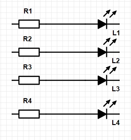
So the resistor and LED in the diagram above have croc-clips on each end to represent the signal head load. And you need four of them because some signal heads have four separate LED strings and each must be tested independently and separately. I will also assume, since you have four LED circuits drawn, that you will have all of these hooked up with croc-clips to terminals on the ECR at the same time. So, getting back to your original question, what value for R1, R2, R3, and R4 do you need to draw 300 mA at 110 VAC through LEDs L1, L2, L3, and L4?

If all the above is correct, then I may have a solution. First, since the excitation voltage is 110 VAC 50 Hz, you need two LEDs, wired in inverse parallel, for each circuit. Second, it would be overkill to provide LEDs capable of passing 300 mA. A small LED operating at 10 to 20 mA is more appropriate for a test rig. Such an LED will typically have a voltage drop of about two volts, which means the remainder of the 110 VAC has to drop across the resistor. Therefore the resistor needs to be about 108/0.02 or about 5.4 kΩ. I would use a 4.7 kΩ or 5.6 kΩ, 10% tolerance, 5 watt, resistor and see if the LED is bright enough to see outside in daylight. If not, use a smaller valued resistor or perhaps a brighter LED. Third, you still need a way to simulate the 300 mA that a real signal head will draw. So place a power resistor of 400 Ω and 50 watt rating in parallel with the resistor-LED string to provide the necessary current, as Chris (@CDRIVE) recommended in post #21.

Perhaps someone can draw a schematic diagram of what I described above.

The "proofing" relay you cited has a coil resistance of 30 Ω so it doesn't consume much power at 300 mA, only about 2.7 watts with a voltage drop of 9 VAC. I neglected that in estimating the series current-limiting resistor for the pair of LED indicators. You may want to include the 30 Ω relay coil resistance in your calculations (always check my calculations!) for both the LED current-limiting resistor as well as the shunt power resistor that actually simulates the signal head and carries most of the "test" current. Put this test rig in a metal box with ventilation holes for convective heat dissipation from the power resistors. Use it only intermittently and allow time for the resistors to cool down in between tests.
 

Herschel Peeler

Feb 21, 2016
401
Joined
Feb 21, 2016
Messages
401
XykCFKr.jpg


Something like this. For the relay to operate then a minimum of 300mA must be drawn.

Why not just use a switch instead of all the circuitry? Maybe I am missing the details of how your current operated relay works. All relays are current operated. Yours draws 300 mA when operated from 110 V?
 

hevans1944

Hop - AC8NS
Jun 21, 2012
4,984
Joined
Jun 21, 2012
Messages
4,984
Why not just use a switch instead of all the circuitry? Maybe I am missing the details of how your current operated relay works. All relays are current operated. Yours draws 300 mA when operated from 110 V?
The relay has a 30 Ω coil and drops about 9 VAC across the coil when 300 mA flows through the coil from the signal head LED load. The relay is used to verify that the signal head actually draws its rated current and is not defective because an LED string in the signal head is open. Because the signal head is powered from 110 VAC, it has to contain many LEDs wired in series to provide enough signal illumination, as well as to drop most of the supply voltage across the LEDs instead of wasting it in a current-limiting resistor. If I were designing the signal head, I would incorporate a constant-current switching supply to further reduce the power lost in a current-limiting resistor. OTOH, power dissipation in an LED signal head might be an advantage in the winter to melt snow and ice accumulation. Point is, there is a lot of power consumed in the signal head, about thirty watts or so. The test rig needs to simulate that. The OP is NOT testing the signal head, he is testing the circuits that drive the signal head.
 

lxlramlxl

Jul 5, 2016
28
Joined
Jul 5, 2016
Messages
28
Okay, I think I see what you are trying to do now. In post #5 you stated:

"you would croc-clip on the circuit to some links.
In reality or you would have is a resistor and an LED in series with clips on either end to put on the positive and negative feed to represent a load."
27cG0sk.jpg


So the resistor and LED in the diagram above have croc-clips on each end to represent the signal head load. And you need four of them because some signal heads have four separate LED strings and each must be tested independently and separately. I will also assume, since you have four LED circuits drawn, that you will have all of these hooked up with croc-clips to terminals on the ECR at the same time. So, getting back to your original question, what value for R1, R2, R3, and R4 do you need to draw 300 mA at 110 VAC through LEDs L1, L2, L3, and L4?

If all the above is correct, then I may have a solution. First, since the excitation voltage is 110 VAC 50 Hz, you need two LEDs, wired in inverse parallel, for each circuit. Second, it would be overkill to provide LEDs capable of passing 300 mA. A small LED operating at 10 to 20 mA is more appropriate for a test rig. Such an LED will typically have a voltage drop of about two volts, which means the remainder of the 110 VAC has to drop across the resistor. Therefore the resistor needs to be about 108/0.02 or about 5.4 kΩ. I would use a 4.7 kΩ or 5.6 kΩ, 10% tolerance, 5 watt, resistor and see if the LED is bright enough to see outside in daylight. If not, use a smaller valued resistor or perhaps a brighter LED. Third, you still need a way to simulate the 300 mA that a real signal head will draw. So place a power resistor of 400 Ω and 50 watt rating in parallel with the resistor-LED string to provide the necessary current, as Chris (@CDRIVE) recommended in post #21.

Perhaps someone can draw a schematic diagram of what I described above.

The "proofing" relay you cited has a coil resistance of 30 Ω so it doesn't consume much power at 300 mA, only about 2.7 watts with a voltage drop of 9 VAC. I neglected that in estimating the series current-limiting resistor for the pair of LED indicators. You may want to include the 30 Ω relay coil resistance in your calculations (always check my calculations!) for both the LED current-limiting resistor as well as the shunt power resistor that actually simulates the signal head and carries most of the "test" current. Put this test rig in a metal box with ventilation holes for convective heat dissipation from the power resistors. Use it only intermittently and allow time for the resistors to cool down in between tests.

Okay, I think I see what you are trying to do now. In post #5 you stated:

"you would croc-clip on the circuit to some links.
In reality or you would have is a resistor and an LED in series with clips on either end to put on the positive and negative feed to represent a load."
27cG0sk.jpg


So the resistor and LED in the diagram above have croc-clips on each end to represent the signal head load. And you need four of them because some signal heads have four separate LED strings and each must be tested independently and separately. I will also assume, since you have four LED circuits drawn, that you will have all of these hooked up with croc-clips to terminals on the ECR at the same time. So, getting back to your original question, what value for R1, R2, R3, and R4 do you need to draw 300 mA at 110 VAC through LEDs L1, L2, L3, and L4?

If all the above is correct, then I may have a solution. First, since the excitation voltage is 110 VAC 50 Hz, you need two LEDs, wired in inverse parallel, for each circuit. Second, it would be overkill to provide LEDs capable of passing 300 mA. A small LED operating at 10 to 20 mA is more appropriate for a test rig. Such an LED will typically have a voltage drop of about two volts, which means the remainder of the 110 VAC has to drop across the resistor. Therefore the resistor needs to be about 108/0.02 or about 5.4 kΩ. I would use a 4.7 kΩ or 5.6 kΩ, 10% tolerance, 5 watt, resistor and see if the LED is bright enough to see outside in daylight. If not, use a smaller valued resistor or perhaps a brighter LED. Third, you still need a way to simulate the 300 mA that a real signal head will draw. So place a power resistor of 400 Ω and 50 watt rating in parallel with the resistor-LED string to provide the necessary current, as Chris (@CDRIVE) recommended in post #21.

Perhaps someone can draw a schematic diagram of what I described above.

The "proofing" relay you cited has a coil resistance of 30 Ω so it doesn't consume much power at 300 mA, only about 2.7 watts with a voltage drop of 9 VAC. I neglected that in estimating the series current-limiting resistor for the pair of LED indicators. You may want to include the 30 Ω relay coil resistance in your calculations (always check my calculations!) for both the LED current-limiting resistor as well as the shunt power resistor that actually simulates the signal head and carries most of the "test" current. Put this test rig in a metal box with ventilation holes for convective heat dissipation from the power resistors. Use it only intermittently and allow time for the resistors to cool down in between tests.

Firstly I'd like to say, forgive my ignorance.

In your first note you mention using two LED's in inverse parallel and then using a 5.4k/4.7k Ohm resisitor and then lastly using a power resistor that CDRIVE suggested.

Is it required that ALL of these are used or could any one be used in the absence of the other.
 

hevans1944

Hop - AC8NS
Jun 21, 2012
4,984
Joined
Jun 21, 2012
Messages
4,984
Is it required that ALL of these are used or could any one be used in the absence of the other.
YES. All are required.

You need a dummy load circuit for each signal-head load you are testing. That circuit consists of a 400 Ω 50 W power resistor connected to your test leads with the croc-clips. This power resistor is also connected in parallel with three other components that are connected in a series and parallel arrangement with each other: a 5.4 kΩ or 4.7 kΩ current-limiting resistor connected in series with two inverse-parallel connected LEDs. The anode of one LED connects to the cathode of the other LED, and the cathode of that one LED connects to the anode of the other LED. This inverse-parallel connection of the two LEDs is necessary for AC operation. The pair of LEDs is then connected in series with the 5.4 kΩ or 4.7 kΩ current-limiting resistor. This circuit is then connected in parallel with the large 400Ω, 50 W, resistor that carries most of the 300 mA current, thereby simulating the signal-head load. The LEDs draw only about 20 mA of current and are there only to tell you voltage is available through the relay coil to operate the signal-head. The current in the relay indicates the circuit is complete by actuating the relay armature through the 400 Ω resistor.

Unless you use two really large, powerfully bright, LEDs capable of handling 300 mA of forward current, and size the current-limiting resistor to drop 99 V at 300 mA, LEDs that draw only about 20 mA instead of 300 mA, wired in parallel with a resistor that draws most of the 300 mA, is the way to go.

Why 99 V? Well, allow 2 V for the LED forward voltage drop at 300 mA, plus 9 V for the 30Ω relay coil voltage drop at 300 mA, and you are left with 99 V to operate the LEDs at 300 mA. That works out to be a total circuit resistance of 330 Ω. At 300 mA this resistor will dissipate 29.7 W. So, might as well go with the 400 Ω 50 W resistor that Chris suggested and use smaller LEDs.

Actually, after allowing for the coil resistance, you need less the 400 Ω to draw 300 mA. 255 Ω would be about right, which is an available 1% tolerance standard value. It would dissipate about 23 W, so a 50 W resistor is appropriate.

Yes, you need all four components: 255 Ω, 50 W resistor; 5.4 kΩ or 4.7 kΩ, 5 W resistor; two LEDs rated for 20 mA forward current wired back-to-back in inverse-parallel connection. Plus a pair of test leads with croc-clips on the ends connected to the whole shebang. Multiply this by however many signal-head loads you need to connect simultaneously.

Are you familiar with Ohm's Law? Series and parallel circuits? LEDs?
 
Last edited:

CDRIVE

Hauling 10' pipe on a Trek Shift3
May 8, 2012
4,960
Joined
May 8, 2012
Messages
4,960
Hop, I was thinking a bit differently about the indicator LED that he wants. Wiring it as you describe will work but it doesn't garantee that the current relay is drawing his required 300mA min. It's unlikely but what I'm saying is if the dummy load resistor ever opened the LED would still light. If he really wants a "current" indicator then one more low value resistor or a string of Diodes in series parallel could be used to drop ~3.5V. Then the LED and its limiting resistor could be wired across the Diodes or low val resistor. This way the LED would be indicating current.

Chris
 

CDRIVE

Hauling 10' pipe on a Trek Shift3
May 8, 2012
4,960
Joined
May 8, 2012
Messages
4,960
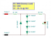
I was describing something like this. Just make believe the probes are Alligator Clips. :)

BTW, I don't understand why you'd need 4 of these (for each signal control head) since your testing the current sensing relay not the LED strings. If I understood you correctly there's only 1 CSR for all the LED strings.

Chris
upload_2016-7-8_0-47-24.png
 
Last edited:

(*steve*)

¡sǝpodᴉʇuɐ ǝɥʇ ɹɐǝɥd
Moderator
Jan 21, 2010
25,510
Joined
Jan 21, 2010
Messages
25,510
one really good option is to place a red LED in parallel with 4 silicon diodes (in series). Two of these can then be placed in inverse parallel.

This can indicate current flow between mA and amps with little change in the brightness of the LED.
 

CDRIVE

Hauling 10' pipe on a Trek Shift3
May 8, 2012
4,960
Joined
May 8, 2012
Messages
4,960
one really good option is to place a red LED in parallel with 4 silicon diodes (in series). Two of these can then be placed in inverse parallel.

This can indicate current flow between mA and amps with little change in the brightness of the LED.
Yes Steve, that's what I was describing in post #32 in place of R2 in my schematic.

Chris
 

lxlramlxl

Jul 5, 2016
28
Joined
Jul 5, 2016
Messages
28
I was describing something like this. Just make believe the probes are Alligator Clips. :)

BTW, I don't understand why you'd need 4 of these (for each signal control head) since your testing the current sensing relay not the LED strings. If I understood you correctly there's only 1 CSR for all the LED strings.

Chris
View attachment 27784

You do technically only need one LED, in fact you don't really need any LEDs at all, just something to draw 300mA.
Just that having an LED for each lamp is aesthetically pleasing.
 

CDRIVE

Hauling 10' pipe on a Trek Shift3
May 8, 2012
4,960
Joined
May 8, 2012
Messages
4,960
You do technically only need one LED, in fact you don't really need any LEDs at all, just something to draw 300mA.
Just that having an LED for each lamp is aesthetically pleasing.
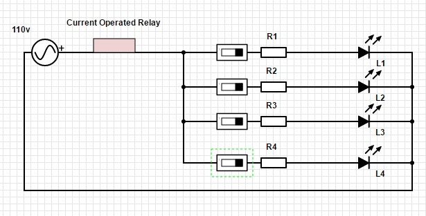
This is what Steve and I are describing.
upload_2016-7-8_10-16-32.png
Now let's talk about this statement...
Just that having an LED for each lamp is aesthetically pleasing
You're confusing me again. Your schematic indicates only 1 current sensing relay in series with paralleled LED strings. Your schematic also indicates that each of those LED strings are activated by it's own relay or SSR, which I presume are switched on and off remotely. You also stated that the CCR requires 300mA min to activate. Therefor each LED string MUST draw 300mA minimum. If all four LED strings are on the total current through the CCR would be 4x300mA = 1.2A.

Now that I've probably confused you too this is my problem. I thought that I understood that the whole idea of this dummy load was to activate the CCR without lighting those LED strings. If this is correct then I can't fathom why more than one LED is "aesthetically pleasing" for testing the CCR. The only way multiple LED indicators make any sense to me is if each (remotely switched) LED string incorporates its own separate CCR.

Chris
 

CDRIVE

Hauling 10' pipe on a Trek Shift3
May 8, 2012
4,960
Joined
May 8, 2012
Messages
4,960
Why not just use a switch instead of all the circuitry? Maybe I am missing the details of how your current operated relay works. All relays are current operated. Yours draws 300 mA when operated from 110 V?
Herschel, I just wanted you to know that this didn't go unnoticed. Agreed, except for SSR's which can be designed to draw just about zilch. ;) On that note he can't use just a switch because his coil Ω is only ~ 30Ω which would pull about 3.7A @ 110VAC.

Chris
 

hevans1944

Hop - AC8NS
Jun 21, 2012
4,984
Joined
Jun 21, 2012
Messages
4,984
Ah! Finally a new schematic from Chris in post #33, and a better one still in post #37. Thank you, Chris. These are much better circuits than what I was thinking of because the LED now actually does something useful, i.e., it lights up when 300 mA of current is drawn through the probes. As @lxlramlxl noted in post #35 you don't really need an LED at all, just a resistor that draws 300 mA or more would suffice. An LED that actually does something other than look aesthetically pleasing is good.

With 20-20 hindsight now, we should all go back and read post #5 where @lxlramlxl explains what he is doing. There is a railroad signal head having multiple independent LEDs, or even incandescent illumination (think different colors if you want to: red,.green, yellow, blue, whatever). Each of these circuits requires a "proving relay" in series with it verify that the light is drawing current when activated. The control box that operates the signal heads contains a proving relay for each independent signal-head circuit, but the box will be some distance away from the signal heads. It could even be in a maintenance shed awaiting test and not connected to any signal head at all. So, to troubleshoot or test it, the technician must substitute dummy loads for the real signal-heads. It would be "nice" to have enough dummy loads to test all the circuits in whatever signal head to which the control box will eventually (or currently) be attached. That may not be practical, but surely there is a minimum number of "dummy loads" that is useful for troubleshooting and test. Perhaps two is sufficient, but it could be more.

Years ago in West Virginia my grandparents lived in a house on a hill adjacent to multiple railroad lines used by freight trains to haul coal mined in West Virginia to steel mills in Pennsylvania. It was a huge operation, and the railroad had many signal heads mounted above as well as adjacent to the tracks to safely direct the trains. Some of these signals were quite complicated, consisting of not just lights (incandescent back then of course) but also semaphore arms. It was fascinating to spend a few hours watching the trains go by and watching for the signals to change. Well, fascinating to me as a young boy back then. Most of the time nothing was happening and the signals didn't change all that often. I later went on and progressed to watching paint dry to pass idle time. But it was important then, as it is now, that the signal heads operate with 100% certainty. Hence the need for "proving" relays to detect open signal-head circuits.

I really hope all this discussion has finally led @lxlramlxl to an acceptable solution. It has certainly been educational and entertaining for me. :D
 

lxlramlxl

Jul 5, 2016
28
Joined
Jul 5, 2016
Messages
28
This is what Steve and I are describing.
View attachment 27790
Now let's talk about this statement...

You're confusing me again. Your schematic indicates only 1 current sensing relay in series with paralleled LED strings. Your schematic also indicates that each of those LED strings are activated by it's own relay or SSR, which I presume are switched on and off remotely. You also stated that the CCR requires 300mA min to activate. Therefor each LED string MUST draw 300mA minimum. If all four LED strings are on the total current through the CCR would be 4x300mA = 1.2A.

Now that I've probably confused you too this is my problem. I thought that I understood that the whole idea of this dummy load was to activate the CCR without lighting those LED strings. If this is correct then I can't fathom why more than one LED is "aesthetically pleasing" for testing the CCR. The only way multiple LED indicators make any sense to me is if each (remotely switched) LED string incorporates its own separate CCR.

Chris

Firstly you would never expect all 3 lights to be light on a traffic light right? Same thing applies here other than you have a double yellow (The four LEDs).
You can do this with just 3 LEDs since the second yellow isn't proved by the current operated relay, all you have to prove is the red, green and first yellow.

I completely agree with you that a single LED would show that the load is enough.
 
Top