So you want to modify your circuit of post #1 to provide a software-switchable output voltage of either 1.2V or 1.0V?
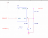
The simple way to do that is to add a second resistor in parallel with R47 which is enabled by a MOSFET. Unfortunately, turning that MOSFET ON will
increase the output voltage, and you really want a circuit where the output voltage is normally 1.2V and
decreases when you signal it.
Here's my suggestion. Put the new resistor normally in circuit by pulling the MOSFET's gate up to the +5V rail. The output voltage will be 1.2V by default, and the MOSFET's gate must be driven to ground to drop the output voltage to 1.0V.

BTW when you post diagrams, you should use GIF or PNG format, not JPG. It wastes space and you get nasty compression artifacts in high contrast areas. Zoom in on your image in post #1 and you'll see the mottled background. Using JPG format also makes it hard for others (i.e. me) to edit without wasting space or making a mess.