I'm having a bit of a brain fog here (and I'm a software guy by trade - this is just a home brew project).
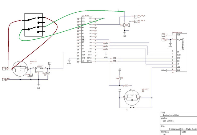
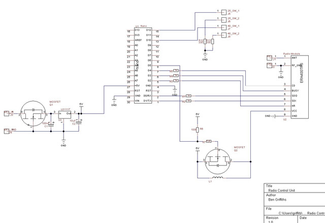
I've got a simple remote control unit (circuit diagram below). Basically; there's two switches, pressing each one sends a message over the air. It's powered by a 9V PP3 battery, regulated down to 5V. I need the remote control to last for serveral hours and even turnign the radio module off when it's not needed. I'm not gettign the battery life I want/need. The uC is an Arduino Nana and the switches I'm using are https://uk.rs-online.com/web/p/push-button-switches/9131706
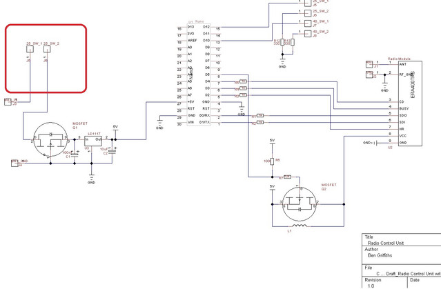
So in my next revision of the board, I only want the system/circuit to be powered when one of the buttons is being held. So my thought was I'd route the battery connection via each switch then somwhow workout which of the switches was being depressed. Sadly I've not got very far as my mind has gone blank on the logic for this (below is as far as I've got)
I'm sure there ust be a simple way of achieving this (and I may even realise over a G+T tonight). But at the moment my mind is blank.
I've got a simple remote control unit (circuit diagram below). Basically; there's two switches, pressing each one sends a message over the air. It's powered by a 9V PP3 battery, regulated down to 5V. I need the remote control to last for serveral hours and even turnign the radio module off when it's not needed. I'm not gettign the battery life I want/need. The uC is an Arduino Nana and the switches I'm using are https://uk.rs-online.com/web/p/push-button-switches/9131706
So in my next revision of the board, I only want the system/circuit to be powered when one of the buttons is being held. So my thought was I'd route the battery connection via each switch then somwhow workout which of the switches was being depressed. Sadly I've not got very far as my mind has gone blank on the logic for this (below is as far as I've got)
I'm sure there ust be a simple way of achieving this (and I may even realise over a G+T tonight). But at the moment my mind is blank.