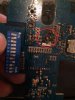
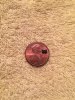
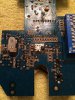
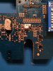
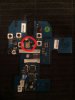
Hi all. I am trying to identify an electronic component on a PCB contained in a remote control transmitter used for a remote controlled helicopter. I have attached a picture of the front and back of the board. The component I am trying to identify is circled in red on one pic. The picture of the other side of the board is also circled in red, so you can see that the other side may have some type of heat sync or radio wave blocking metal foil (?).
It is 2.3 mm x 4.14 mm in rectangular size and has what appears to be three soldered legs on one side and the other side appears to be soldered/grounded to the foil. It also has these numbers/letters stamped on the top of the component: K5 741. A search does not come up with anything under those numbers.
My searches have led me to believe it is possibly a transistor or a transformer. I have also attached the schematic diagram. The part I think it is is labeled as "Q4". I cannot find the designated electronics symbol for Q4, so that is why I am confused as to what it is. The parts list for this component has this information on it: Footprint: MOS-N1, Part Type: RD01, Designator: Q4.
The reason I need to know the part is because I have another of the same transmitter with that particular component burnt, along with the resistor positioned on the board directly off of the 12v dc power supply. I can identify the resistor.
If you can identify the component, is there a way to determine a replacement?
Thanks in advance for your reply.
")