3V To 5V Boost DC-DC Converter using MAX711
- Rajkumar Sharma
- 5.412 Views
- easy
- Tested
- SKU: EL94650
- Quote Now
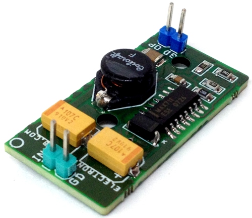
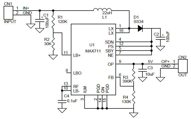
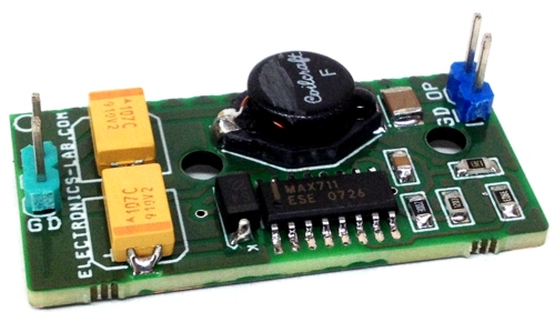
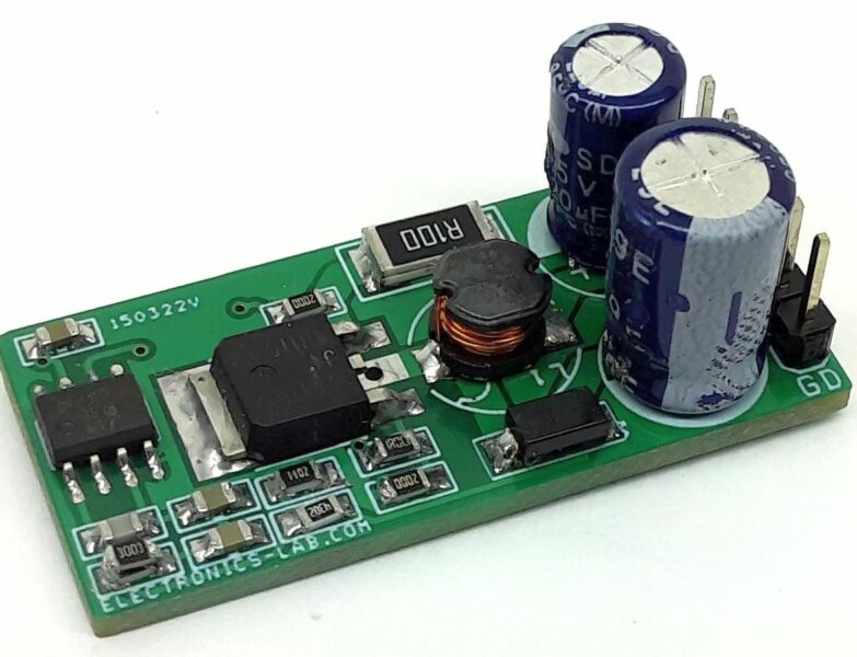
The circuit shown here is a compact and high-efficiency boost converter that has been designed for hand-held equipment. This boost converter converts 2 cells (3V) DC power into 5V DC with output load current up to 500mA. Typical efficiency when boosting battery inputs is 85%. The circuit is based on MAX711 which integrates a step-up DC-DC converter with a linear regulator to provide step-up voltage conversion. The circuit is optimized for battery applications where the input varies above and below the regulated output voltage. The project has an input range from +1.8V to +11V. The circuit is set for 5V output but it has an adjustable output that can be set from +2.7V to +5.5V with the help of two R3, R4 resistors. The IC contains a comparator for low battery detection. If the voltage at LBI+ falls below that at LBI- (typically connected to REF), LBO goes low. Hysteresis is typically 50mV. You can set the low-battery monitor’s threshold with two resistors, R1 and R2.
The MAX711 integrate a step-up DC-DC converter with a linear regulator to provide step-up/down voltage conversion. The step-up switch-mode regulator contains an N-channel power MOSFET switch. It also shares a precision voltage reference with a linear regulator that contains a P-channel MOSFET pass element. Step-Up Operation A pulse-frequency-modulation (PFM) control scheme with a constant 1μs off-time and variable on-time controls the N-channel MOSFET switch. The N-channel switch turns off when the part reaches the peak current limit or the 4μs maximum on-time. The ripple frequency is a function of load current and input voltage.
Features
- Supply Input Two AA Cell- 3V DC (+1.8V to +11V Range)
- Output 5V DC (Adjustable 2.5V to 5.5V)
- Output Load 500mA Maximum
- Efficiency for battery input is 85%
Schematic
Parts List
Connections


