4 Channel Current Sense Amplifier – Low and High-Side Voltage Output
This 4-Channel current sense amplifier is designed for cost-optimized applications. This is a current-sense amplifier (also called a current-shunt monitor) that senses the voltage drop across current-sense resistors at common-mode voltages from –0.2 V to +26 V, independent of the supply voltage.
This 4-Channel current sense amplifier is designed for cost-optimized applications. This is a current-sense amplifier (also called a current-shunt monitor) that senses the voltage drop across current-sense resistors at common-mode voltages from –0.2 V to +26 V, independent of the supply voltage. The project was built using INA4180 chip which integrates a matched resistor gain network in four, fixed-gain 20V/V, this matched gain resistor network minimizes gain error and reduces the temperature drift. The board operates with a single 2.7-V to 5.5-V power supply. The four-channel INA4180 draws a maximum supply current of 900 µA. Resistors R2, R6, R8, R12, R3, R7, R9, R13 and Capacitor C3, C4, C5, C6 used as input filters. The gain of the amplifier is 20V/V, and external input resistors resulting a 0.9% gain error.
Gain Selection
- INA4180A1 Gain 20V/V
- INA4180A2 Gain 50V/V
- INA4180A3 Gain 100V/V
- INA4180A4 Gain 200V/V
Features
- Operating Power Supply 2.7V to 5V DC 10mA
- Output 0.2V/A (2V @ 10Amps)
- Common-mode voltage -0.2V To 26V
- Input offset (±) (max) (µV) 150
- Input offset drift (±) (typ) (µV/°C) 0.2
- Voltage gain (V/V) 20
- CMRR (min) (dB) 84
- Bandwidth (kHz) 350
- Gain error (%) 8
- Gain error drift (±) (max) (ppm/°C)20
- On Board Power LED
- Screw Terminal for Current Sense Load
- Header Connector for Logic supply and Outputs
- PCB Dimensions 47.78 x 36.20 mm
- 4 x 2.5MM Mounting Holes
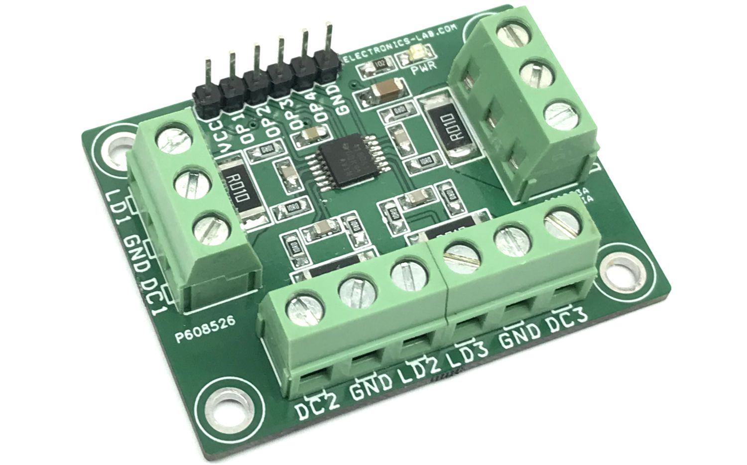
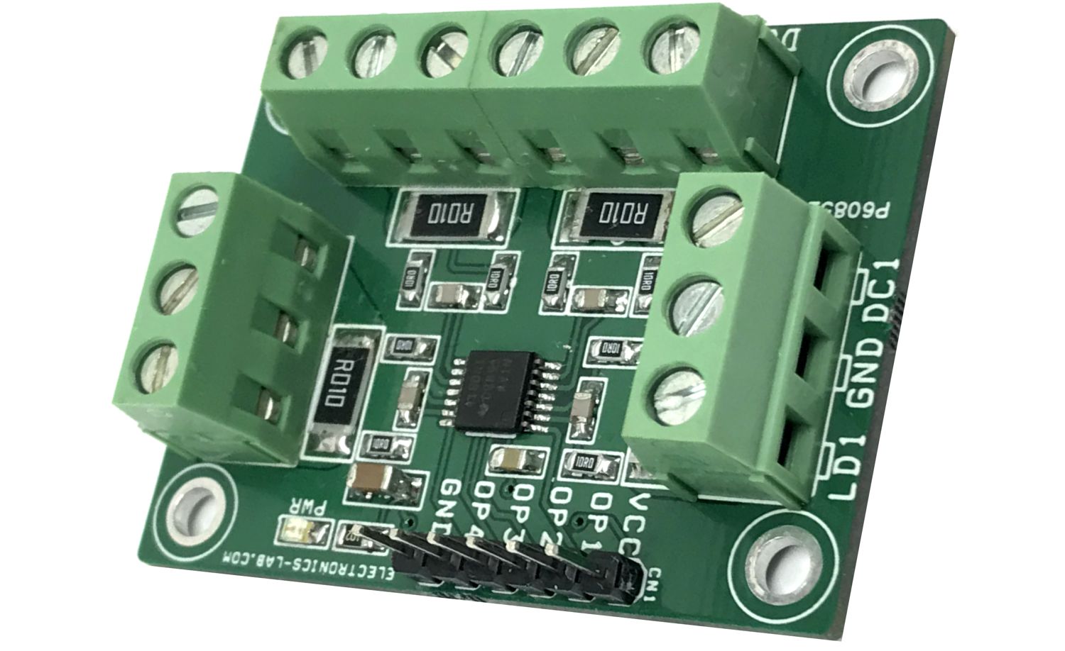
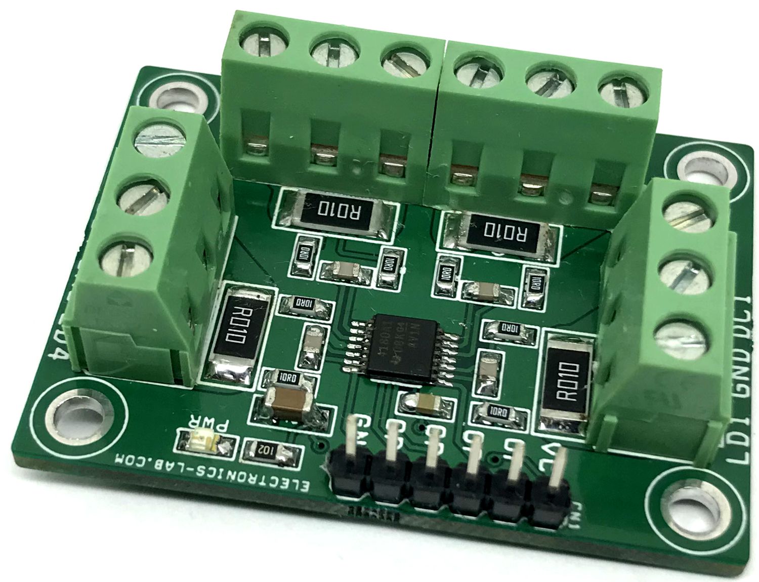
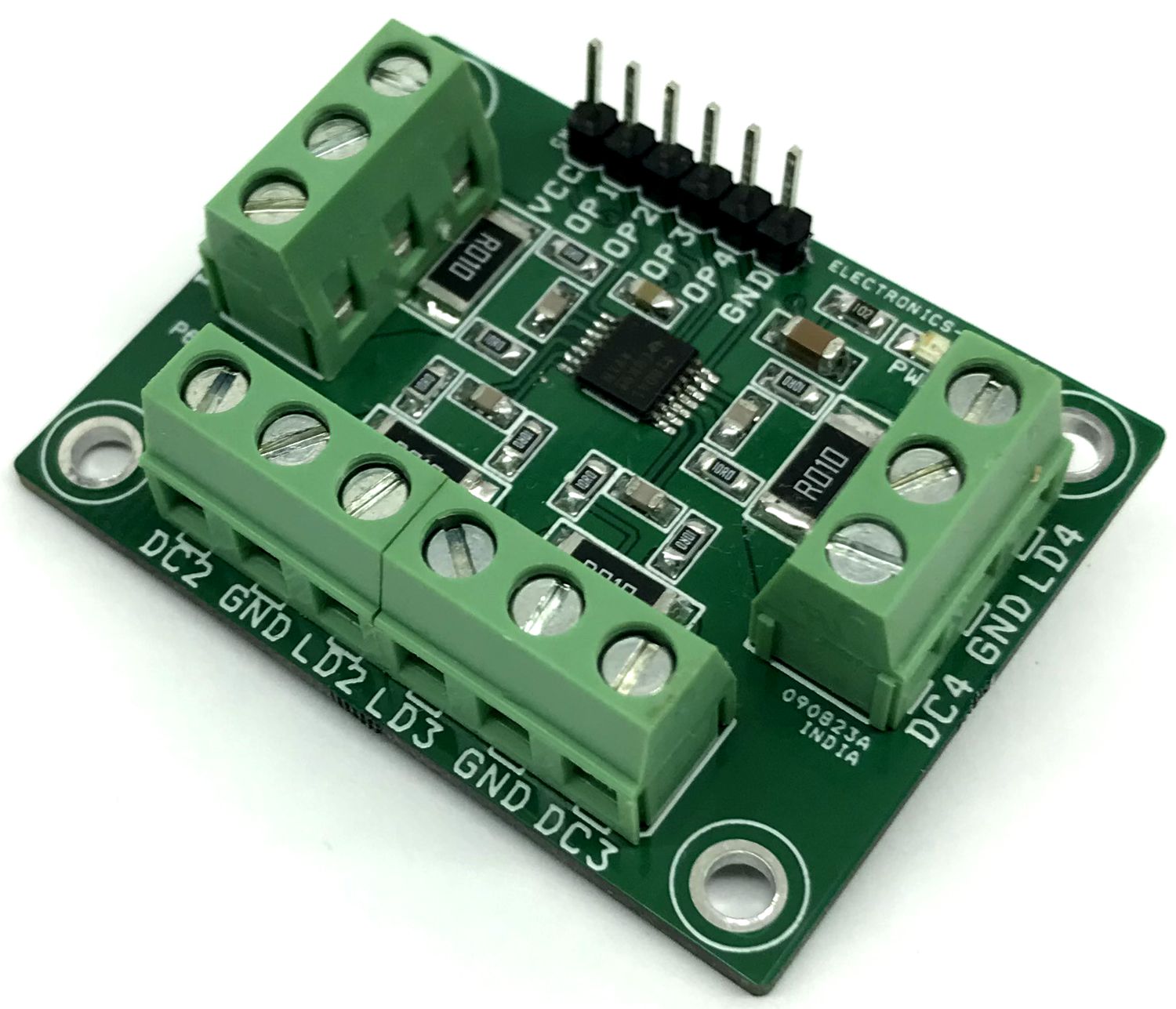
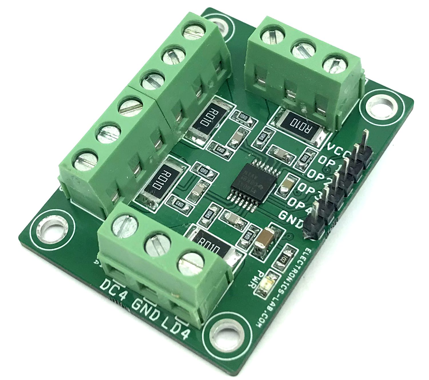
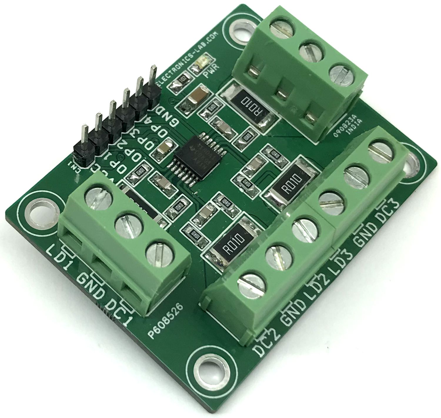
Connections and Other Details
- CN1: Pin 1 = VCC 2.7V to 5.5V Dc Input, Pin 2 = Output 1, Pin 3 = Output 2, Pin 4 = Output 3, Pin 5 = Output 4, Pin 6 = GND
- CN2: Pin 1 = Load 1, Pin 2 = GND, Pin 3 = DC 1 Input
- CN3: Pin 1 = Load 4, Pin 2 = GND, Pin 3 = DC 4 Input
- CN4: Pin 1 = Load 2, Pin 2 = GND, Pin 3 = DC 2 Input
- CN5: Pin 1 = Load 3, Pin 2 = GND, Pin 3 = DC 3 Input
- D1: Power LED
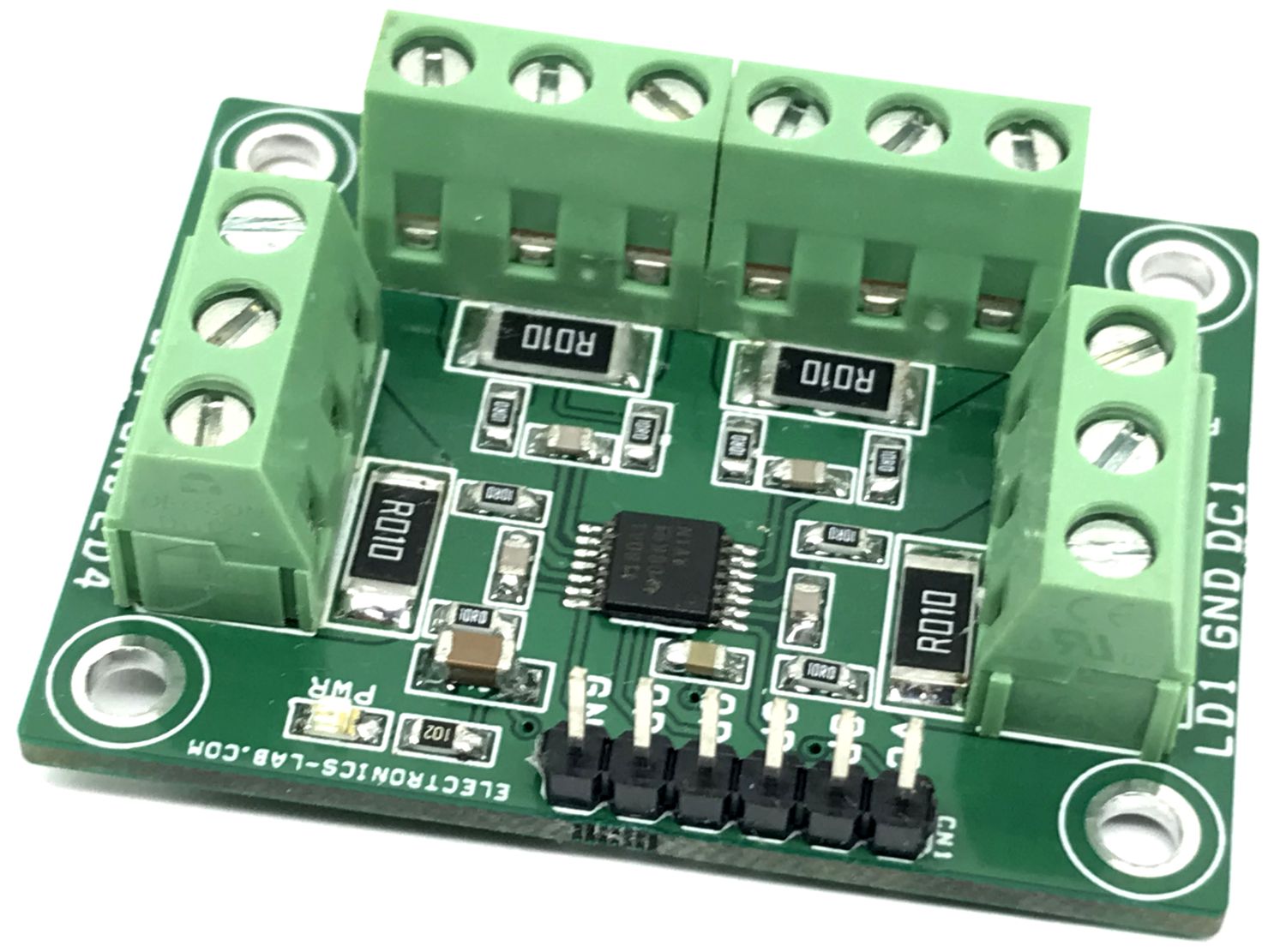
RSENSE and Device Gain Selection
The project is tested with 4 x 0.01Ω/3W current resistors, considering approx. current sense range up to 10A. The users may choose the appropriate current sense resistor and Amplifier with different gains as per requirement. Refer to the datasheet of the chip for more info. The accuracy of the INA4180 is maximized by choosing the current-sense resistor to be as large as possible. A large sense resistor maximizes the differential input signal for a given amount of current flow and reduces the error contribution of the offset voltage. However, there are practical limits as to how large the current-sense resistor can be in a given application. The INA4180 has a typical input bias current of 80 µA for each input when operated at a 12V common-mode voltage input. When large current-sense resistors are used, these bias currents cause increased offset error and reduced common-mode rejection. Therefore, using current-sense resistors larger than a few ohms is generally not recommended for applications that require current-monitoring accuracy. A second common restriction on the value of the current-sense resistor is the maximum allowable power dissipation that is budgeted for the resistor.
Schematic
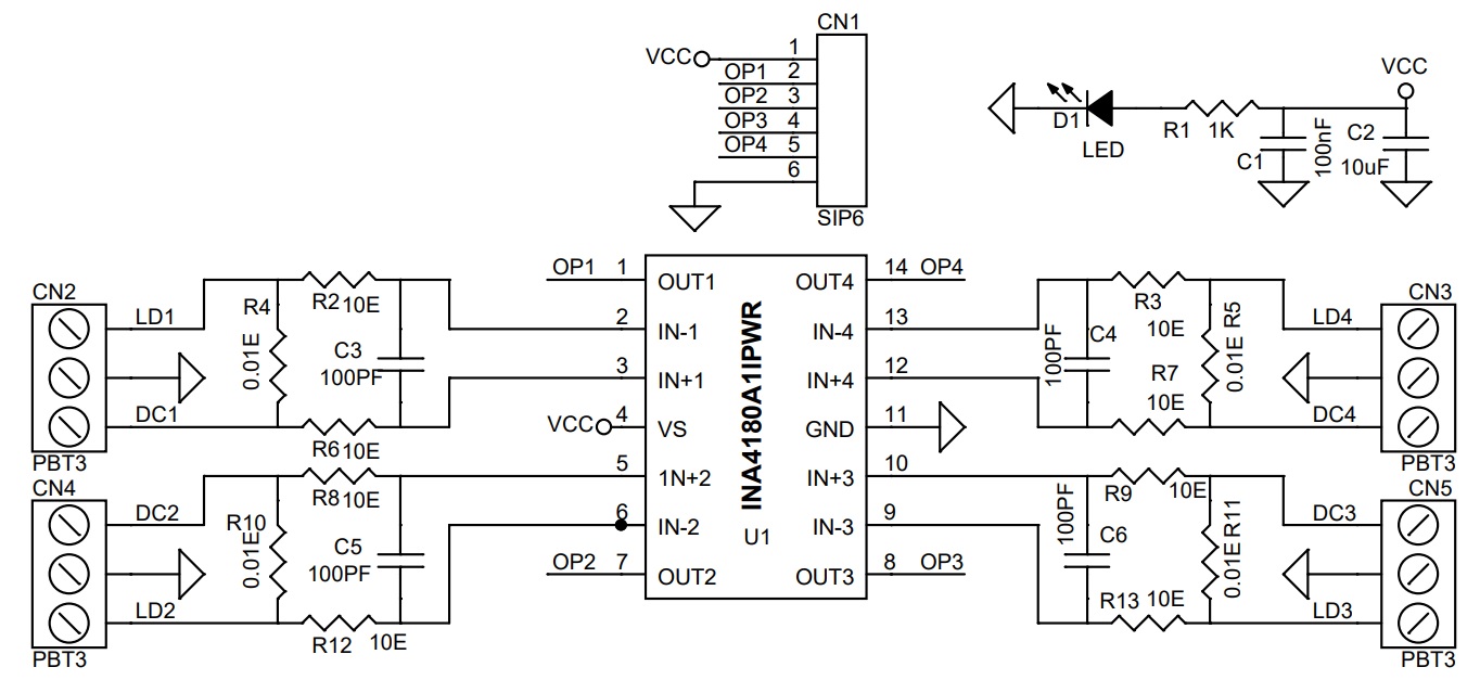
Parts List
| NO | QNTY. | REF. | DESC. | MANUFACTURER | SUPPLIER | SUPPLIER PART NO |
|---|---|---|---|---|---|---|
| 1 | 1 | CN1 | 6 PIN MALE HEADER PITCH 2.54MM | WURTH | DIGIKEY | 732-5319-ND |
| 2 | 4 | CN2,CN3,CN4,CN5 | 3 PIN SCREW TERMINAL PITCH 5.08MM | PHOENIX | DIGIKEY | 277-1248-ND |
| 3 | 1 | C1 | 100nF/50V CERAMIC SMD SIZE 0805 | YAGEO/MURATA | DIGIKEY | |
| 4 | 1 | C2 | 10uF/25V CERAMIC SMD SIZE 1206 | YAGEO/MURATA | DIGIKEY | |
| 5 | 4 | C3,C4,C5,C6 | 100PF/50V CERAMIC SMD SIZE 0805 | YAGEO/MURATA | DIGIKEY | |
| 6 | 1 | D1 | LED RED SMD SIZE 0805 | OSRAM | DIGIKEY | 475-1278-1-ND |
| 7 | 1 | R1 | 1K 5% SMD SIZE 0805 | YAGEO/MURATA | DIGIKEY | |
| 8 | 8 | R2,R3,R6,R7,R8,R9,R12,R13 | 10E 5% SMD SIZE 0805 | YAGEO/MURATA | DIGIKEY | |
| 9 | 4 | R4,R5,R10,R11 | 0.01E/3W 1% SMD SIZE 2512 | BORNS INC | DIGIKEY | CRA2512-FZ-R010ELFCT-ND |
| 10 | 1 | U1 | INA4180A1IPWR | TI | DIGIKEY | 296-49094-1-ND |
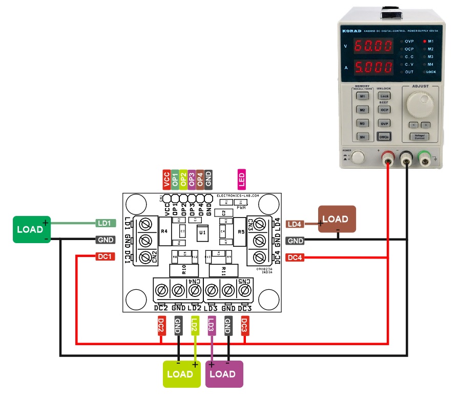
Connections
Gerber View
Photos