Bluetooth Robot Car Controller using ESP32
- Rajkumar Sharma
- 96 Views
- medium
- Tested
- SKU: EL144152
- Quote Now
- 0 Likes

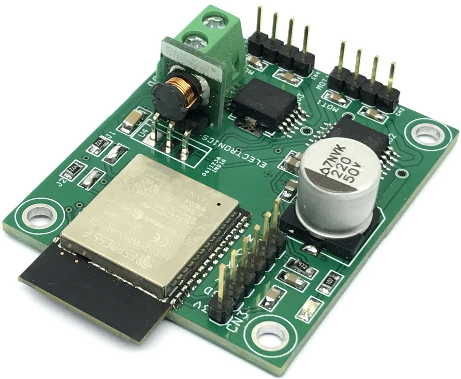
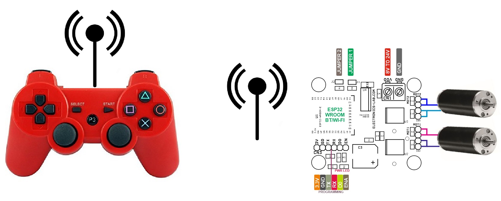
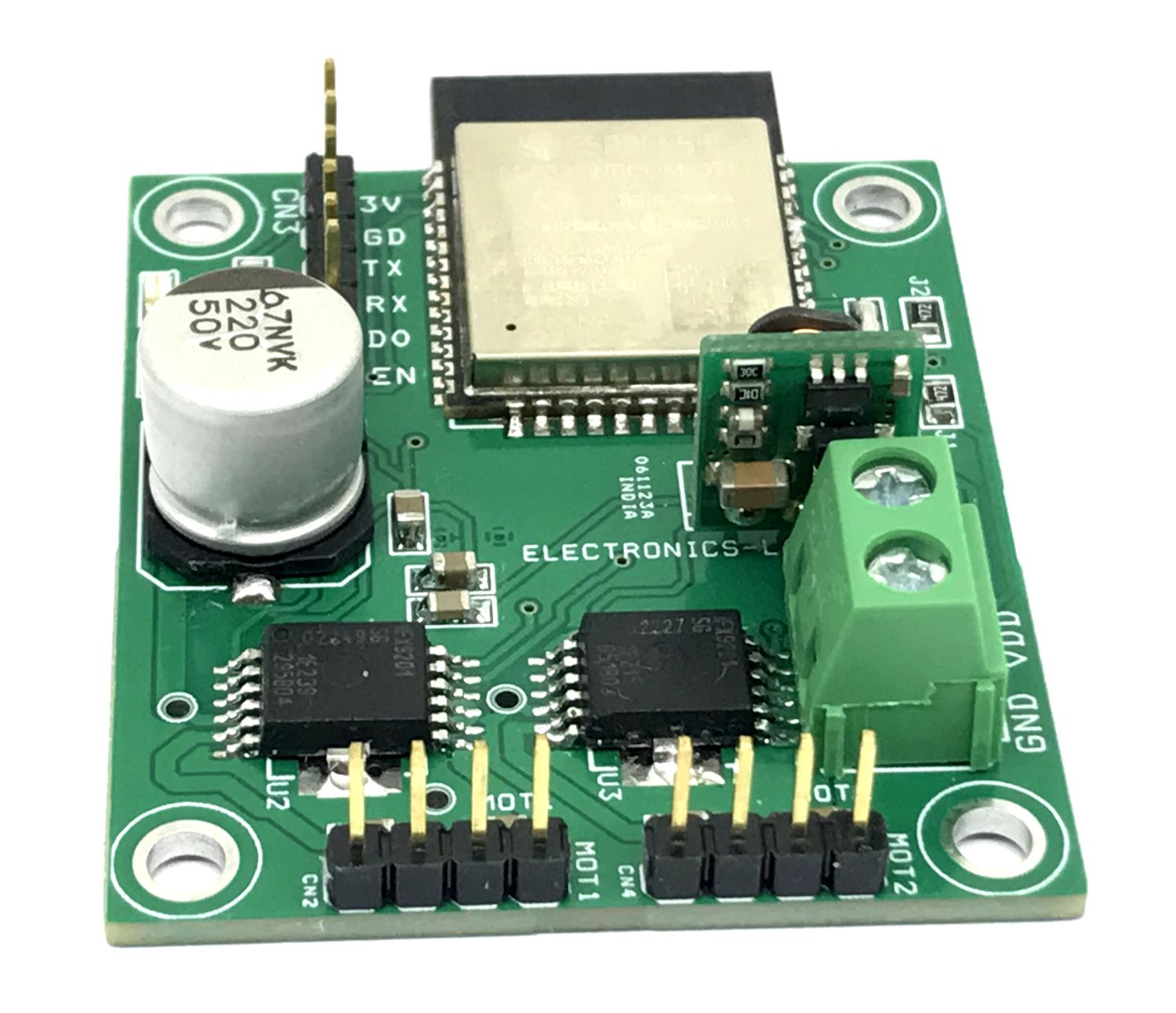
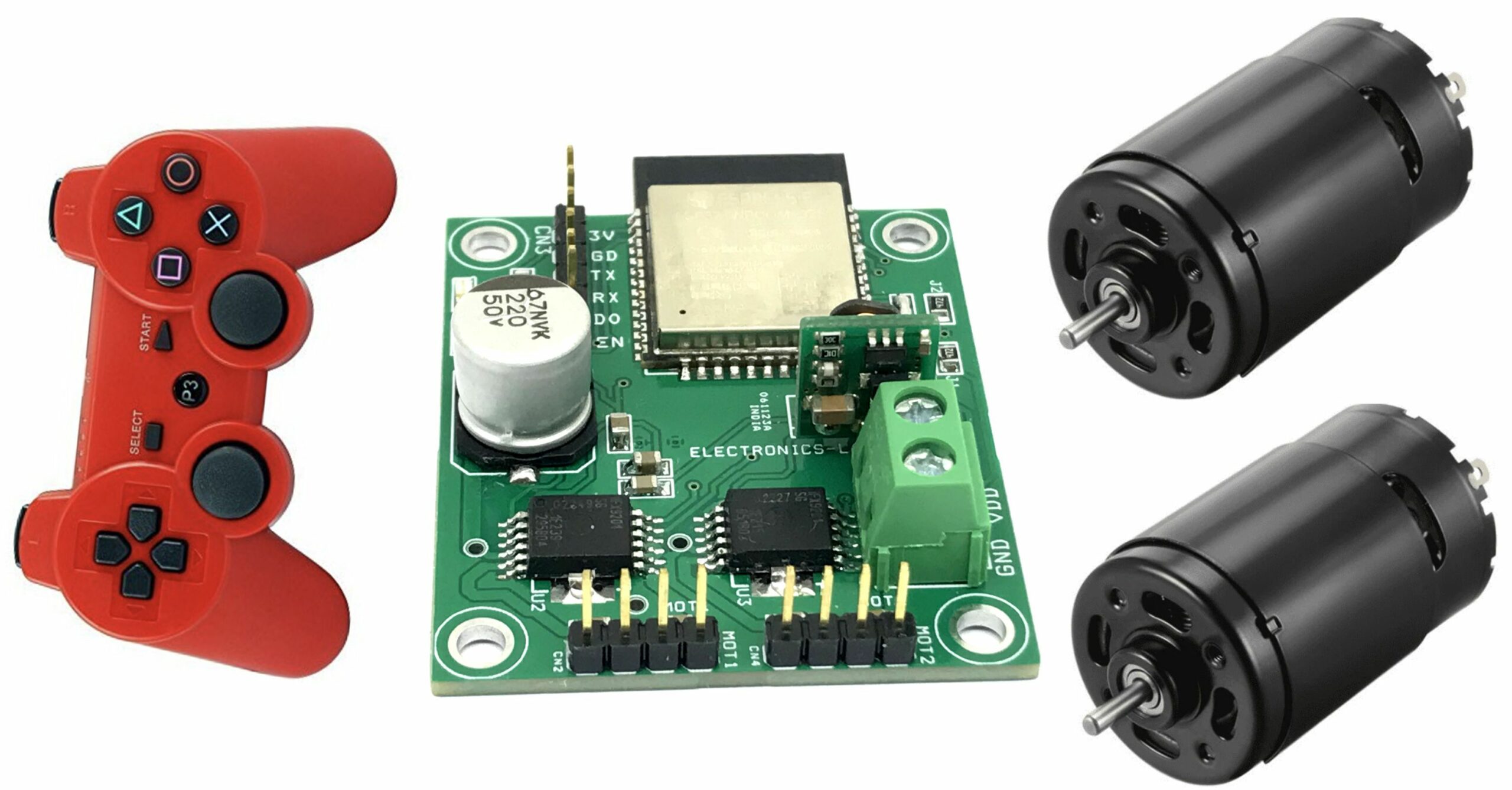
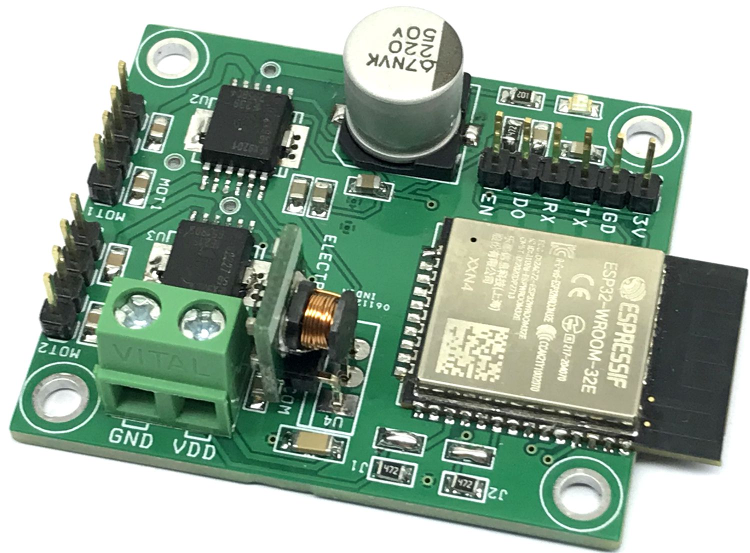
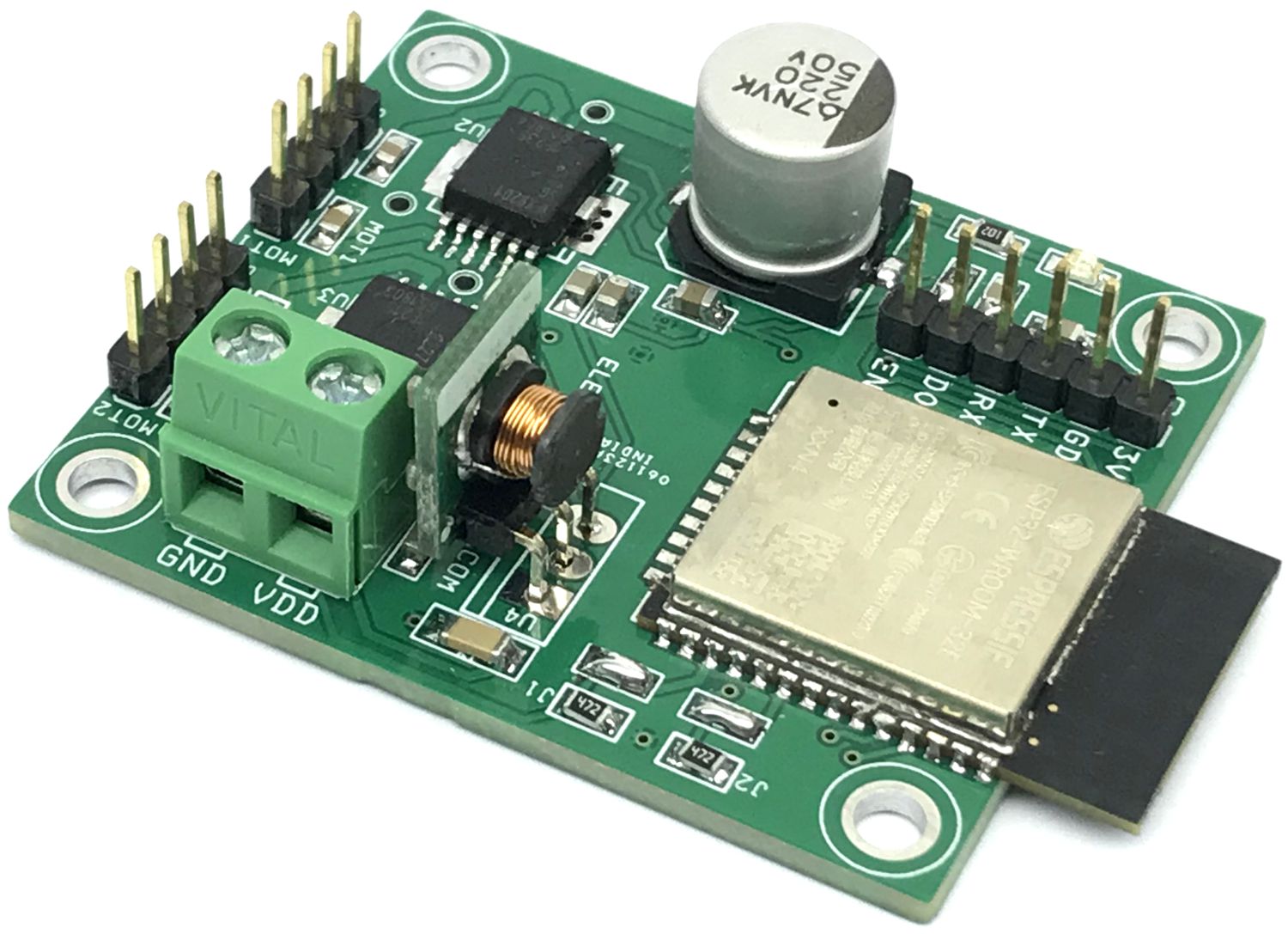
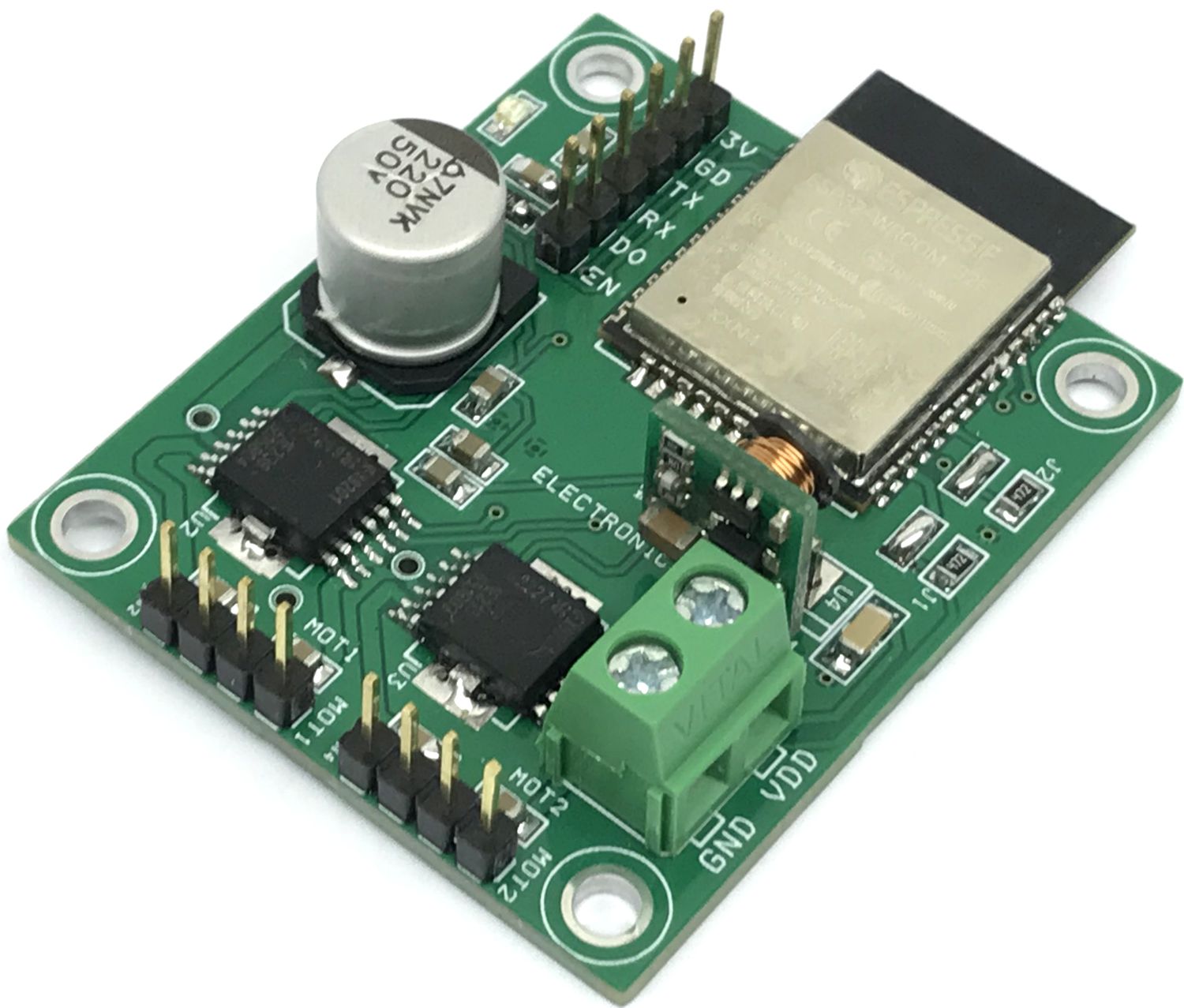
This wireless robot car controller board is built using an ESP32 BT/Wi-Fi module, 2 x H-Bridges, 3.3V regulator. It also includes an ESP32 programming connector, power LED, screw terminal connector for the power supply, header connector for motors, and high-value capacitors on the DC supply for smooth motor operations. The operating power supply is 8V to 24V DC. The project has two H-brides and each can drive 2.5A continues. The board is suitable for small and medium-sized robot cars. It is an open-source hardware project that can be programmed as per requirement. ESP32 I/O details are available in descriptions. ESP32 supports Bluetooth connectivity and the robot car can be controlled using a small phone, Laptop, or Tablet. The project was built using an ESP32-Wroom processor and this chip supports Bluetooth and Wi-Fi connectivity.
The project can be tested with example Arduino code which is provided below. The user will be able to drive a robot car with a PS3 Bluetooth remote. Refer to the link below to learn more about PS3 and ESP32 pairing, and ESP32 programming under Arduino IDE.
https://dronebotworkshop.com/ps3-esp32/
Features
- Power Supply 8V to 24V DC
- Motor Load d up to 2.5A, Peak 6Amps Each Motor
- Over Current Shutdown Threshold 8Amps
- No Heatsink for H-Bridge
- PWM Frequency Up to 20Khz (Tested), ESP32 Default Output 500Hz
- Board Power LED
- Overtemperature Shut down with Latch Behaviour, H-Bridge
- Short Circuit Shut Down with Latch Behaviour, H-Bridge
- Chopper Current Limitation, H-Bridge
- VDD Undervoltage Shutdown
- 4 x 3 mm Mounting Holes
- PCB Dimensions 48.90 x 41.28 mm
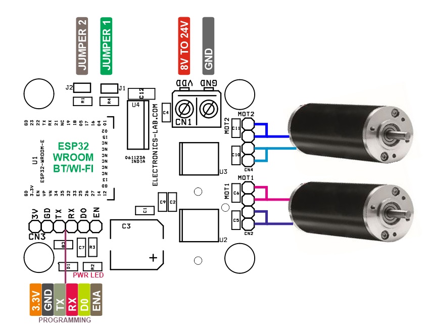
Connections
- CN1: Pin 1 VDD 8V to 24V, Pin 2 = GND
- CN2: Pin 1 & 2 = Motor 1, Pin 3 & 4 = Motor 1
- CN3: Pin 1 = 3.3V, Pin 2 = GND, Pin 3 = TX, Pin 4 = RX, Pin 5 = GPIO0, Pin 6 = Enable (Programming Connector)
- CN4: Pin 1 & 2 = Motor 2, Pin 3 & 4 = Motor 2
- J1: Jumper Closed (Pull Low) = Enable, can be controlled using ESP32 Pin GPIO16 Pin High = Disables Motor 1
- J1: Jumper Closed (Pull Low) = Enable, can be controlled using ESP32 Pin GPIO18 Pin High = Disables Motor 2
- D1: Power LED
- U4: 3.3V Regulator, Provides 3.3V to ESP32 processor input from Motor Supply 8V to 24V
- U2: H-Bridge Motor Driver, Motor 1
- U3: H-Bridge Motor Driver, Motor 2
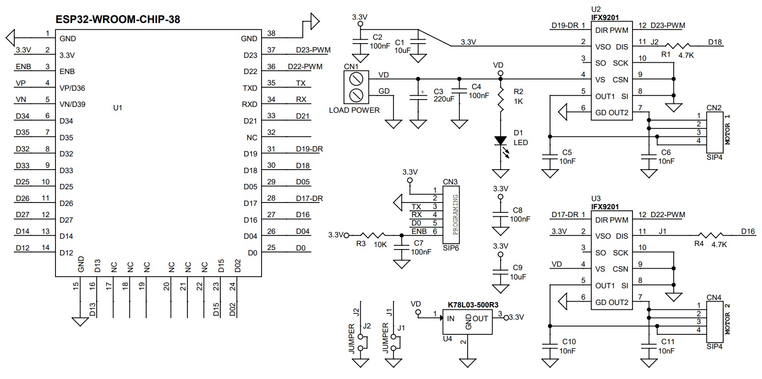
ESP32 Pins Vs H-Bridge U2 and U3 Pins
- GPIO23/D23-PWM = U2 PWM, Motor 1
- GPIO22/D22-PWM = U3 PWM, Motor 2
- GPIO19/D19-DR = U2 Direction Control High or Low, Motor 1
- GPIO17/D17-DR = U3 Direction Control High or Low, Motor 2
- GPIO16/D16 = Motor2 Enable/Disable (Solder Jumper J1 = Enable), DE-solder Jumper J1 for ESP32 Enable/Disable Control
- GPIO18/D18 = Motor1 Enable/Disable (Solder Jumper J2 = Enable), DE-solder Jumper J1 for ESP32 Enable/Disable Control
Schematic
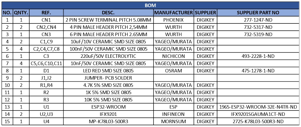
Parts List
| NO. | QNTY. | REF. | DESC. | MANUFACTURER | SUPPLIER | SUPPLIER PART NO |
|---|---|---|---|---|---|---|
| 1 | 1 | CN1 | 2 PIN SCREW TERMINAL PITCH 5.08MM | PHOENIX | DIGIKEY | 277-1247-ND |
| 2 | 2 | CN2,CN4 | 4 PIN MALE HEADER PITCH 2,54MM | WURTH | DIGIKEY | 732-5317-ND |
| 3 | 1 | CN3 | 6 PIN MALE HEADER PITCH 2.65MM | WURTH | DIGIKEY | 732-5319-ND |
| 4 | 2 | C1,C9 | 10uF/10V CERAMIC SMD SIZE 0805 | YAGEO/MURATA | DIGIKEY | |
| 5 | 4 | C2,C4,C7,C8 | 100nF/50V CERAMIC SMD SIZE 0805 | YAGEO/MURATA | DIGIKEY | |
| 6 | 1 | C3 | 220uF/50V ELECTROLYTIC | NICHICON | DIGIKEY | 493-2228-1-ND |
| 7 | 4 | C5,C6,C10,C11 | 10nF/50V CERAMIC SMD SIZE 0805 | YAGEO/MURATA | DIGIKEY | |
| 8 | 1 | D1 | LED RED SMD SIZE 0805 | OSRAM | DIGIKEY | 475-1278-1-ND |
| 9 | 2 | J1,J2 | JUMPER- PCB SOLDER | |||
| 10 | 2 | R1,R4 | 4.7K 5% SMD SIZE 0805 | YAGEO/MURATA | DIGIKEY | |
| 11 | 1 | R2 | 1K 5% SMD SIZE 0805 | YAGEO/MURATA | DIGIKEY | |
| 12 | 1 | R3 | 10K 5% SMD SIZE 0805 | YAGEO/MURATA | DIGIKEY | |
| 13 | 1 | U1 | ESP32-WROOM | ESP | DIGIKEY | 1965-ESP32-WROOM-32E-N4TR-ND |
| 14 | 2 | U2,U3 | IFX9201 | INFINEON | DIGIKEY | IFX9201SGAUMA1CT-ND |
| 15 | 1 | U4 | MP-K78L03-500R3 | MORNSUM | DIGIKEY | 2725-K78L03-500R3-ND |
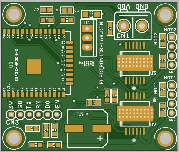
Connections
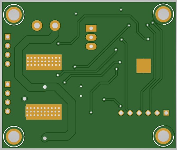
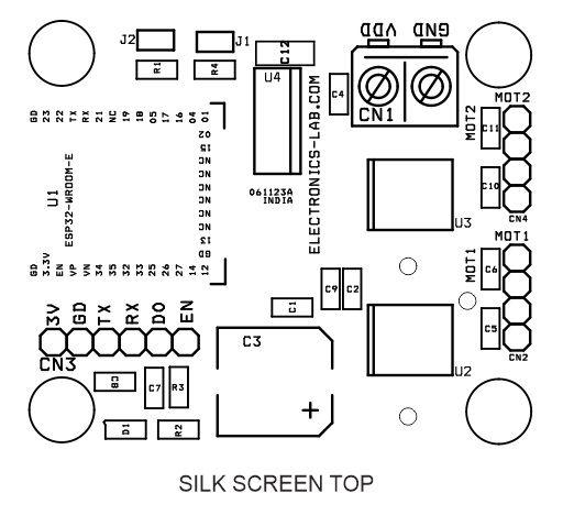
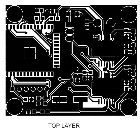
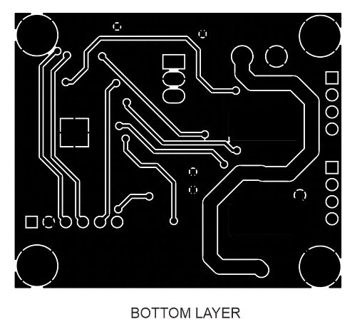
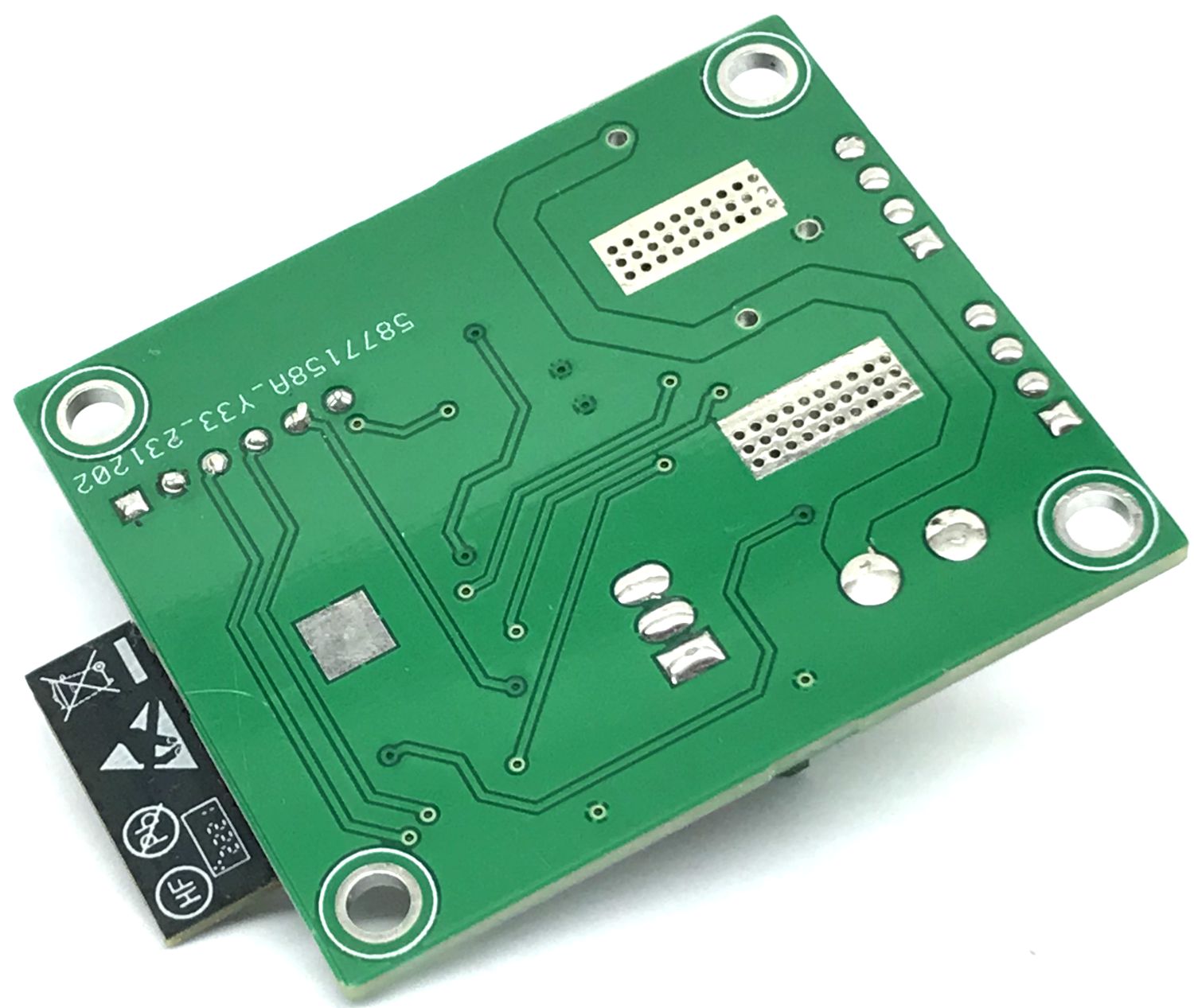
Gerber View
Photos
Video
IFX9201 Datasheet
PCB