Brushed DC Motor Speed and Direction Controller Using Joystick
This DC Motor controller provides direction and speed control of a brushed DC motor using a Joystick. This is an Arduino compatible open-source hardware with various applications.

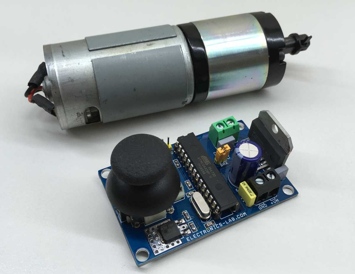
This DC Motor controller provides direction and speed control of a brushed DC motor using a Joystick. This is an Arduino compatible open-source hardware with various applications. It can be used to control scissor lift motor, Linear actuator, Camera slider, camera pan-tilt head, curtain motor, power window motor, robotics, smart furniture automation, hospital furniture automation, projector up/down controller, TV up/down controller are few application examples. The board provides superb performance, smooth movement of motor, and hassle-free use. You only need to connect the motor wires, power the board, and you ready to go.
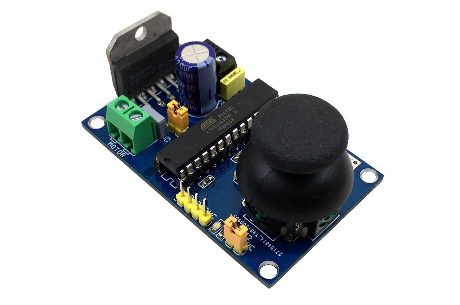
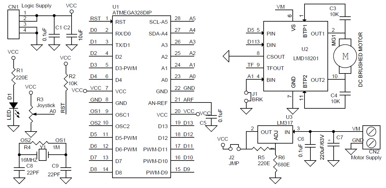
The controller has 3 main elements, Atmega328 Micro-Controller, LMD18201 DC Motor H-bridge, and Joystick connected to A0 Analog pin of microcontroller. This board can control DC motor up to 48V DC with continuous current up to 3A and peak current 6A.
Arduino Code
It is an Arduino compatible hardware and a new Atmega328 chip requires the burning of Bootloader to upload the Arduino code. Follow the below link for more info on programming and boot-loader burning.
The example code drives the DC motor with a joystick. I have used only 2 pins of LMD18201 chip, PWM, and Direction pin, I have not used the break pin, close the J1 jumper to free the break option of LMD182001. Open the jumper J1 in some applications if the user wants to use the Break option.
Click the download link at the end of the article to download the Arduino example code and test this hardware.
Arduino Pins Vs LMD18201 Motor Driver Pins
Arduino Digital D5>>PWM Pin LMD18201, Arduino Digital Pin D11 >> Direction Pin LMD18201, Analog Pin A1 >> Break Pin LMD18201, Analog pin A0 >> One Axis-Joystick
Power Supply
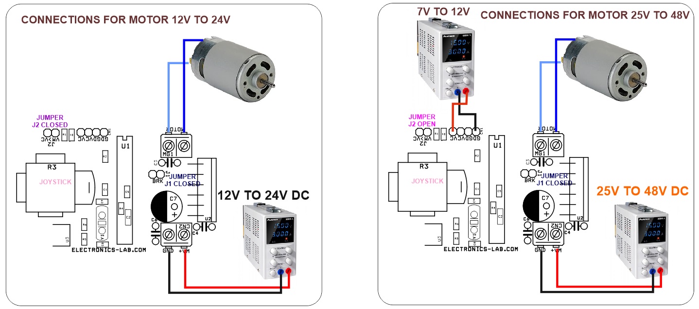
To run a 12V to 24V motor, the board requires a single power supply of 12V to 24V DC. To use this option Close the jumper 2 and power the CN2 wih 12V to 24V. To drive a Higher voltage motor, the circuit requires 2 separate power supplies, one for logic and one motor, in this case open the J2 jumper, use CN2 to apply motor supply 25V to 48V and CN1 7V to 24V logic supply.
Heat-sink
If you want to fetch full power from LMD18201 IC it is advisable to use a large size heatsink on the IC.
Features
- Operating Power Supply 12V to 24V DC (for Motor 25V to 48V Power Refer to Note)
- D1 Power LED
- Joystick: Motor Direction CW/CCW and Speed Control
- PWM Duty Cycle Adjustable 0 to 100% (Frequency 975Hz)
- On Board Regulator L317 to Power 5V DC to Atmega328 Chip
LMD18201
The LMD18201 is a 3A H-Bridge designed for motion control applications. The device is built using a multi-technology process which combines bipolar and CMOS control circuitry with DMOS power devices on the same monolithic structure. The H-Bridge configuration is ideal for driving DC and stepper motors. The LMD18201 accommodates peak output currents up to 6A. Current sensing can be achieved via a small sense resistor connected in series with the power ground lead. For current sensing without disturbing the path of current to the load, the LMD18200 is recommended.
Schematic
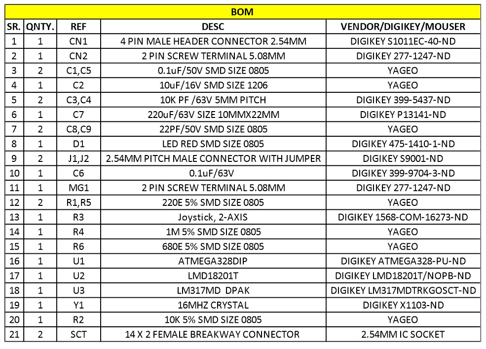
Parts List
Connections
Gerber View
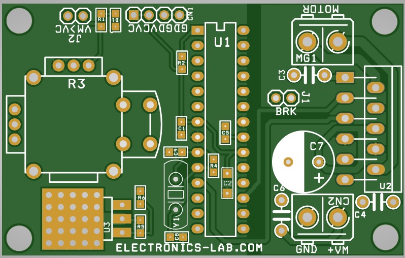
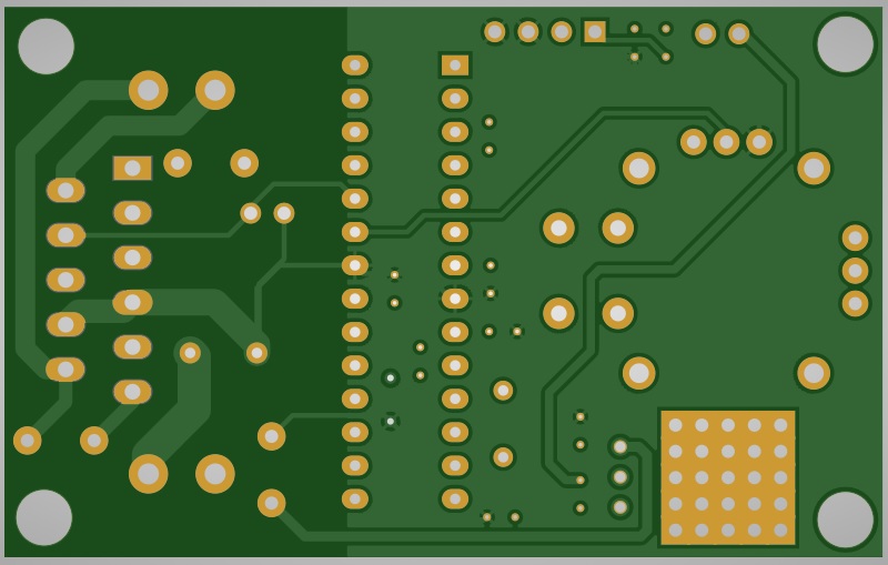
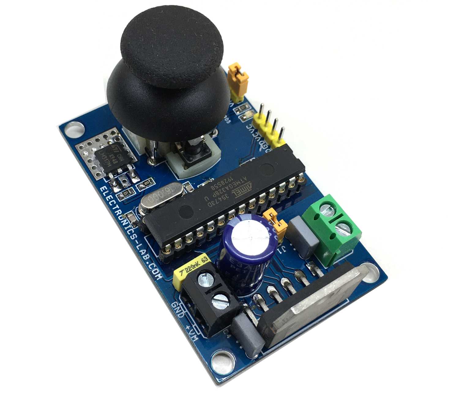
Photos