Color OLED SSD1331 Display with Arduino Uno
Display technology is constantly approving, from the days of the 16x2 LCD to today of the various cool displays like the E-paper and OLED displays, efforts keep going to make them even better, with more colors and lower power consumption among other features. This makes them the perfect component for user interface in electronic projects.
Display technology is constantly approving, from the days of the 16×2 LCD to today of the various cool displays like the E-paper and OLED displays, efforts keep going to make them even better, with more colors and lower power consumption among other features. This makes them the perfect component for user interface in electronic projects. Monochrome OLED displays are a product of such advancement and we have used them in a couple of projects on this website but despite the fact that they are low power, quite bright and easy to use, they are monochromatic, which means they have one or a few colors available. So I was quite excited when I came across a colored OLED display and felt it will be a great idea to make ta tutorial on how to use this display in Arduino projects.
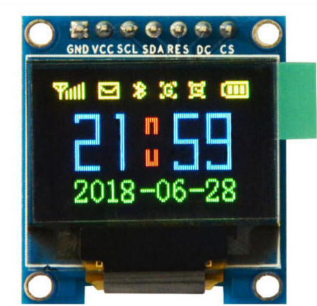
For today’s tutorial, we will use the 0.95″, SSD1331 based colored OLED display. This display, just like all other OLED displays, is low power (consumes just 25mA when all the pixels are on) and offers brightness levels greater than what is available with LCDs. It has a resolution of 96×64 pixels and can display over 65000 different colors. It communicates over SPI, which means, asides from VCC and GND, it will use 5 of the Arduino GPIO pins.
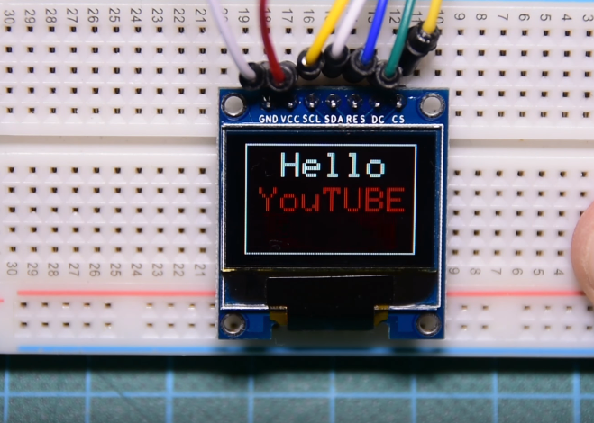
To demonstrate how to use this display in your projects, we will create a simple sketch which will show a YouTube subscribe button on it. The code will be properly explained, so it is easy for you to modify and adapt it to the needs of your projects.
Required Components
The following components are required for this project;
As usual, the exact components used for this tutorial can be purchased via the links attached to them.
Schematics
The schematic for this tutorial is quite easy as it involves just the OLED display and the Arduino. Connect the OLED display to the Arduino as shown in the schematics below.
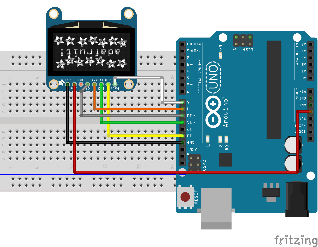
To make room for variations in pin labels and make the schematics easier to follow, the connections between the Arduino and the OLED display is further described below.
OLED - Arduino
GND - GND
Vin/VCC - 5V
SCL/CLK - D13
SDA/MOSI - D11
RES/RST - D9
DC - D8
CS - D10
Ensure the connections are as described above. You can check the datasheet of your display in case the pin labels does not match the one above.
Code
The code for this tutorial is heavily depended on the Adafruit SSD1331 OLED driver library for Arduino. The library was created specifically for use with displays that are based on the SSD1331 display driver. I created a demo sketch for this tutorial and will go over the functions and statements in detail so you can learn how to adapt it for use in your own projects. In addition to the SSD1221 OLED library, we will also use the Adafruit GFX Library along with the Arduino SPI library.
As usual, we start by including the libraries that will use on our sketch. After this, we declare the pins of the Arduino to which the pins of the OLED are connected and also declare variables to hold some of the colors that we will use.
#include <Adafruit_GFX.h>
#include <Adafruit_SSD1331.h>
#include <SPI.h>

#define sclk 13
#define mosi 11
#define cs   10
#define rst  9
#define dc   8

// Color definitions
#define  BLACK           0x0000
#define BLUE            0x001F
#define RED             0xF800
#define GREEN           0x07E0
#define CYAN            0x07FF
#define MAGENTA         0xF81F
#define YELLOW          0xFFE0
#define WHITE           0xFFFF
Next, we create an object of the Adafruit SSD1331 library with the DC, CS and RST pins as arguments.
Adafruit_SSD1331 display = Adafruit_SSD1331(cs, dc, rst);
Next is the void setup() function. We use the display.begin() function to start communications with the display. With this done, we use the display.fillScreen() function to create and switch between multiple backgrounds for the display. To display text, we use the display.print() function with display.setTextColor() and display.setTextSize() to respectively set its color and font size. All of these functions were used to create a Youtube subscribe button.
void setup() {

  display.begin();
  display.fillScreen(RED);
  delay(300);
  display.fillScreen(GREEN);
  delay(300);
  display.fillScreen(BLUE);
  delay(300);
  display.fillScreen(BLACK);
  delay(1000);
  display.setCursor(20,5);
  display.setTextColor(WHITE);
  display.setTextSize(2);
  display.print("Hello");

  display.setCursor(8,25);
  display.setTextColor(RED);
  display.setTextSize(2);
  display.print("YouTUBE");

  display.fillRect(10,40, 75, 20, RED);

  display.setCursor(20,47);
  display.setTextColor(WHITE);
  display.setTextSize(1);
  display.print("Subscribe");

  display.drawRect(0,0,96,64,WHITE);
  delay(1000);
}
Up next is the void loop() function. The code under the loop function is similar to that of the setup() function. We created two boxes, one with a black background and the other with a red background using the display.fillRect() function. Then we wrote the text “subscribe” on it using the display.setCursor() function to position the text.
void loop()
{
  display.fillRect(10,40, 75, 20, BLACK);
  delay(1000);
  display.fillRect(10,40, 75, 20, RED);
  display.setCursor(20,47);
  display.setTextColor(WHITE);
  display.setTextSize(1);
  display.print("Subscribe");
  delay(1000);
}
The complete code for the project is available below and also attached under the download section.
#include <Adafruit_GFX.h>
#include <Adafruit_SSD1331.h>
#include <SPI.h>

#define sclk 13
#define mosi 11
#define cs   10
#define rst  9
#define dc   8

// Color definitions
#define  BLACK           0x0000
#define BLUE            0x001F
#define RED             0xF800
#define GREEN           0x07E0
#define CYAN            0x07FF
#define MAGENTA         0xF81F
#define YELLOW          0xFFE0
#define WHITE           0xFFFF

Adafruit_SSD1331 display = Adafruit_SSD1331(cs, dc, rst);

void setup() {

  display.begin();
  display.fillScreen(RED);
  delay(300);
  display.fillScreen(GREEN);
  delay(300);
  display.fillScreen(BLUE);
  delay(300);
  display.fillScreen(BLACK);
  delay(1000);
  display.setCursor(20,5);
  display.setTextColor(WHITE);
  display.setTextSize(2);
  display.print("Hello");

  display.setCursor(8,25);
  display.setTextColor(RED);
  display.setTextSize(2);
  display.print("YouTUBE");

  display.fillRect(10,40, 75, 20, RED);

  display.setCursor(20,47);
  display.setTextColor(WHITE);
  display.setTextSize(1);
  display.print("Subscribe");

  display.drawRect(0,0,96,64,WHITE);
  delay(1000);
}

void loop()
{
  display.fillRect(10,40, 75, 20, BLACK);
  delay(1000);
  display.fillRect(10,40, 75, 20, RED);
  display.setCursor(20,47);
  display.setTextColor(WHITE);
  display.setTextSize(1);
  display.print("Subscribe");
  delay(1000);
}
There are several other functions in the SSD1331 Arduino library that you may find useful for your projects. You can check all the functions and their usage in the library documentation here.
Demo
Copy the code and upload to your Arduino Uno. Ensure everything is connected as described under the schematics section. If you follow the steps correctly, you should see your screen come up as shown below.
That’s it for this tutorial guys. What cool projects do you think will be a perfect fit for this display? Ensure you drop a comment.
As usual, the video version of this tutorial is available on youtube.
I had to change your code to include all 5 connections to Arduino
Adafruit_SSD1331 display = Adafruit_SSD1331(cs, dc, mosi, sclk, rst);
to get it to work on my display
Thanks for the feedback. You are welcome.
i am getting this error when i try to compile my sketch:
expected ‘,’ or ‘…’ before numeric constant
he is giving this error in line 1-5 from the code. what can i do to fix that error
U gotta rename pinout static name #DEFINEs, and the params in function Adafruit_SSD1331 too. (eg. cs -> csa) Maybe since then Adafruit has changed its library inside?