

Dual Output Adjustable Linear Power Supply +/-1.2V to +/-12V @ 250mA
- Rajkumar Sharma
- 981 Views
- easy
- Tested
- SKU: EL113051
- Quote Now
- 0 Likes

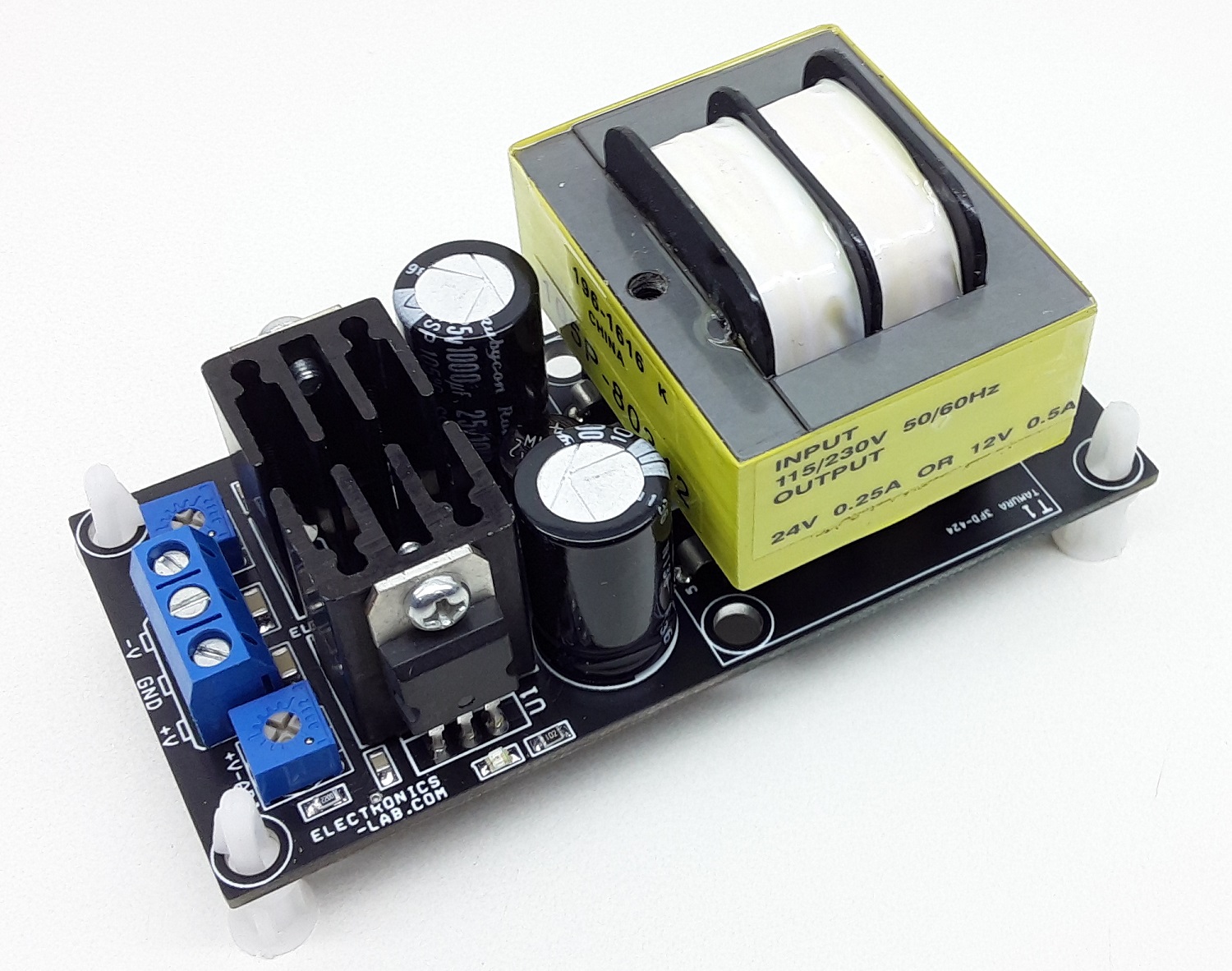
This project is a solution to power up most devices or projects requiring dual (+/-) adjustable power. The circuit consists of a stepdown transformer, bridge rectifier, DC filter capacitors, LM317 positive and LM337 negative adjustable voltage regulators, 2 x trimmer pot for independent output voltage adjust, and power LEDs.
Parts Explanation
- Connector CN1 : 230V/115V AC Input
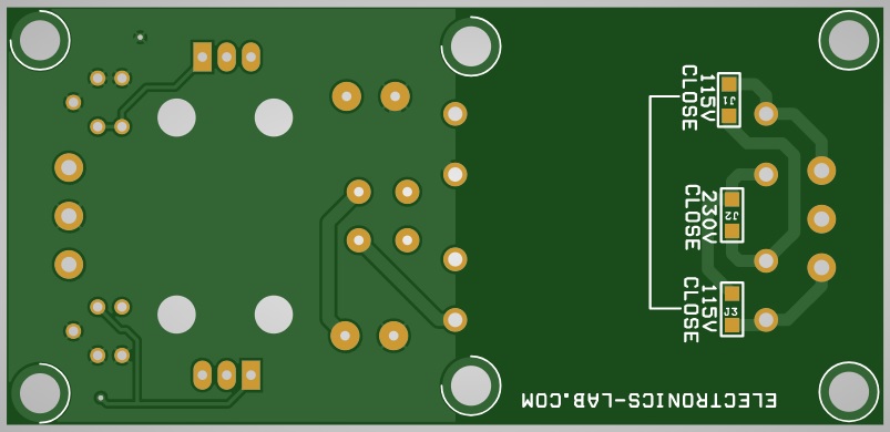
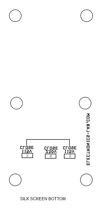
- Jumper J2 : 230V Selection
- Jumper J1 & J3 : 115V Selection
- Transformer T1 : Step Down Transformer 12V-0-12VAC Output, 230V/115V AC Input
- Bridge Rectifier BR1 : Rectifier Converts DC in to AC Supply
- Capacitors C3, C5 : DC Filter Capacitors
- LED D1 : +V PWR LED
- LED D2 : -V PWR LED
- Resistor R1, R2 : Current Limiting Resistors For LEDs D1 and D2
- Regulator U1 : +V Adjustable Regulator
- Regulator U2 : -V Adjustable Regulator
- Trimmer Pot PR1 : +V Output Adjust +1.2V to +12V
- Trimmer Pot PR2 : -V Output Adjust -1.2V to -12V
- Capacitor C1, C2, C4, C6 : DC Filter Capacitors
- Connector CN2 : Adjustable DC Output
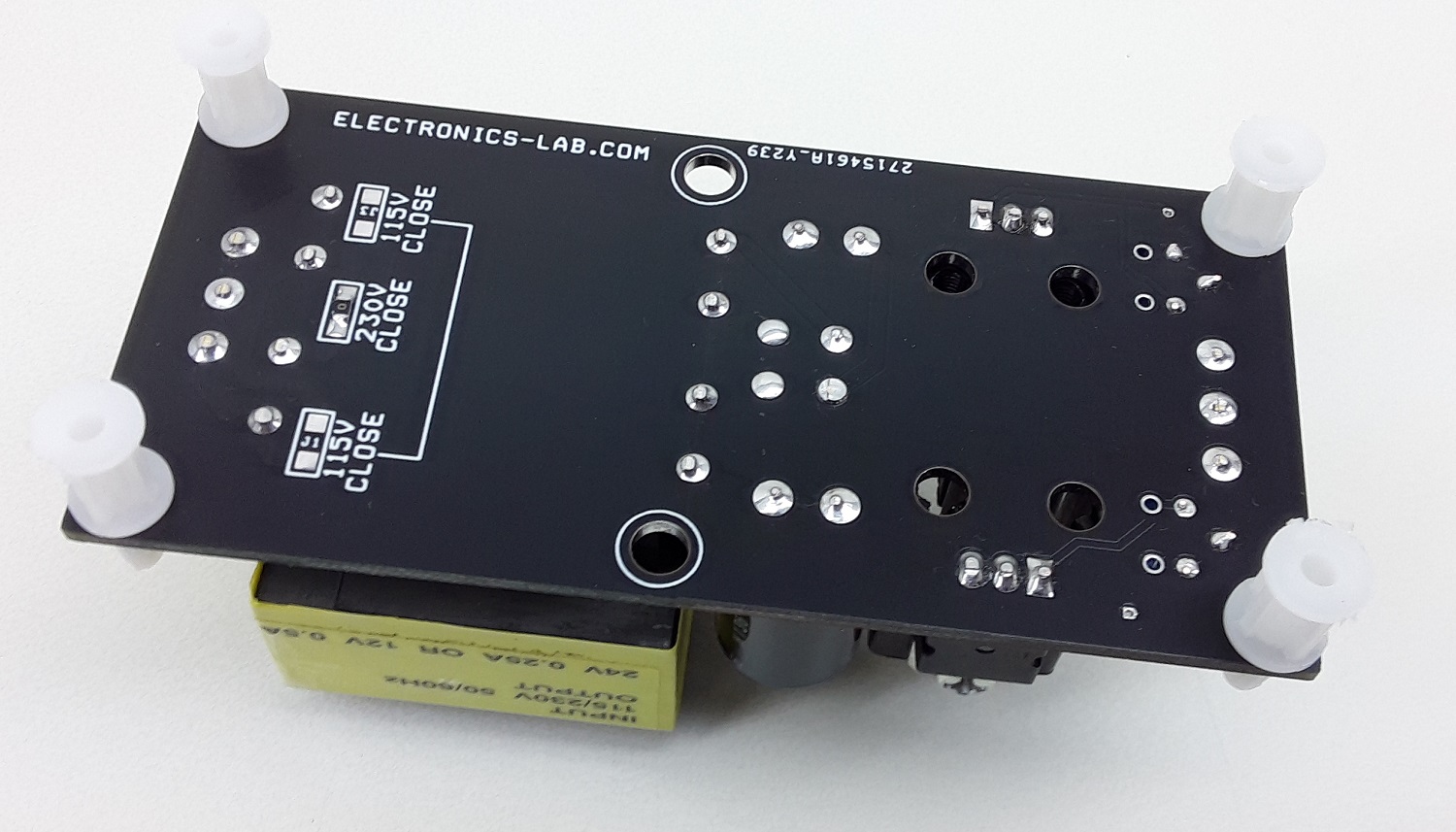
Note1: This power supply supports 230V AC or 115V AC input, Jumpers are located under PCB for input voltage selection, remove input power cable while changing Jumper selection.
Note 2: This power supply contains hazardous voltage at the input, PCB must be installed in an encloser that prevents accidental contact. Use Plastic screws to mount the PCB
Note 3: Heatsink is a must for regulators U1 and U2 @ full load, the heatsink should be mounted with plastic screws and should not touch the ground plane of the PCB.
Note 4: It is advisable to set the output voltage using PR1 and PR2 before connecting the output to the load.
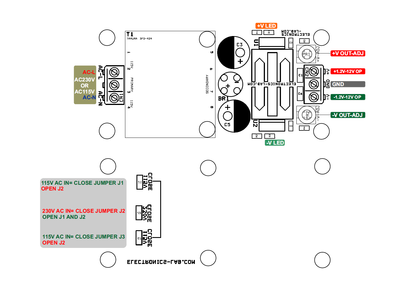
Input Voltage Selection
- For 230V AC Input: Close Jumper J2, Jumper J1, and J3 Open
- For 115V AC Input: Close Jumper J1 and J3, Jumper J2 Open
Other Similar AC to DC Power Supplies
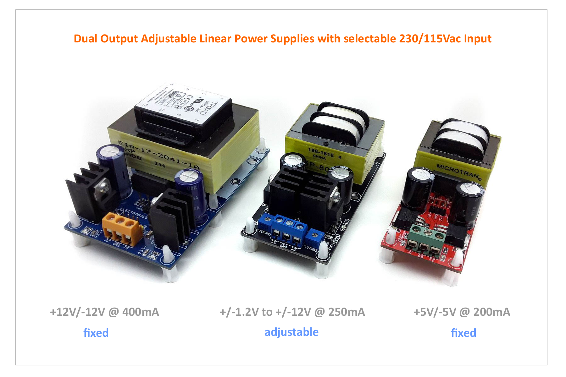
- Dual +5 V/-5V @ 200 mA Regulated Linear Power Supply
- Dual +12V/-12V @ 400mA Regulated Linear Power Supply with AC input
Features
- Input 230V or 115V AC (Use Jumpers to Select 230V or 115V AC)
- Output +/-1.2V to 12V DC (Dual Output)
- Output Ripple Approx. 5mV
- Maximum Load Current 500mA (250mA + 250mA)
- 2 X Power LEDs, for +V and -V
- Screw Terminal for AC Input
- Screw Terminal for Regulated DC Output
- PCB Dimensions 91.76 x 43.82 mm
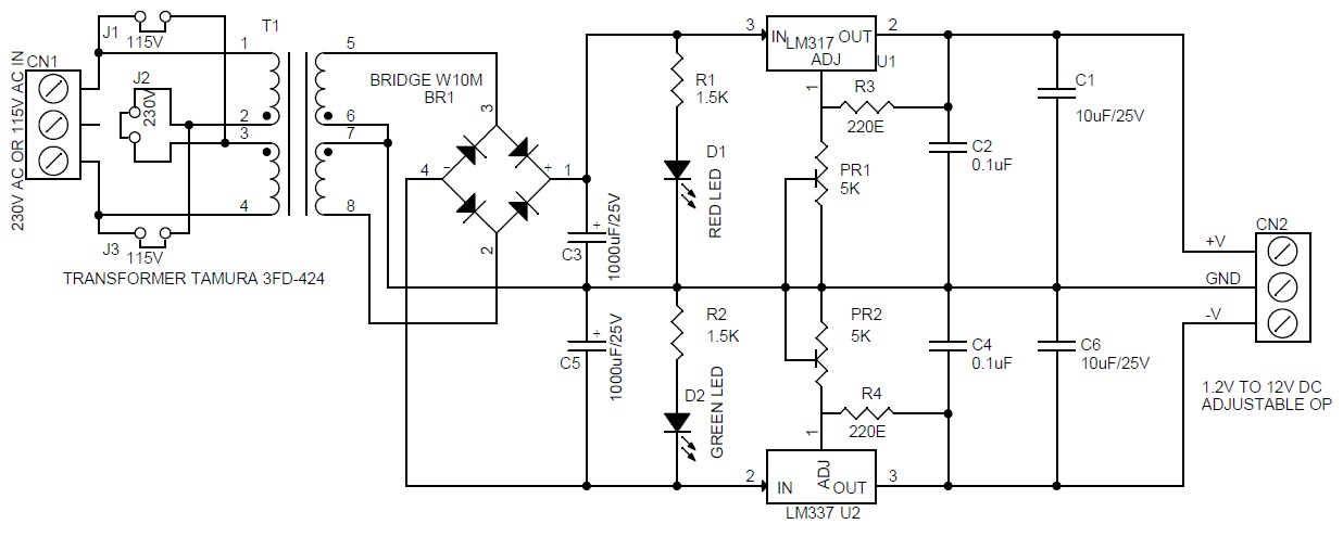
Schematic
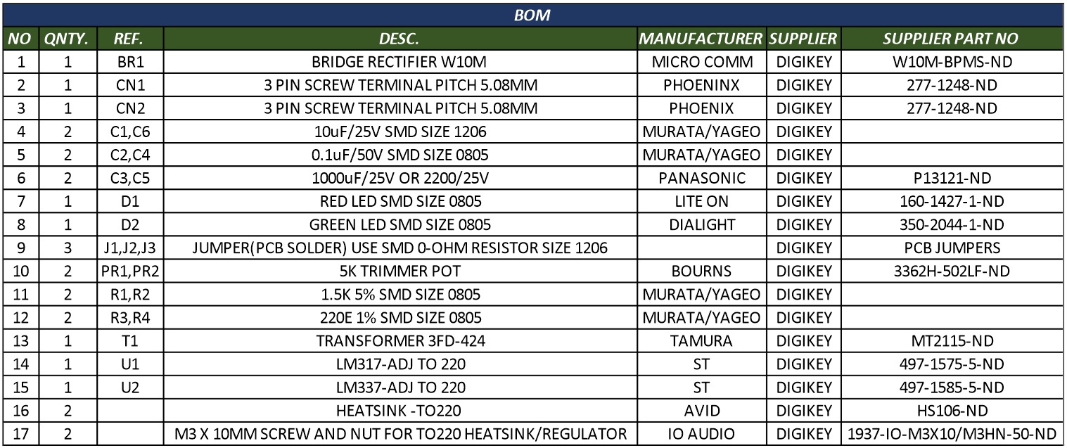
Parts List
| NO | QNTY. | REF. | DESC. | MANUFACTURER | SUPPLIER | SUPPLIER PART NO |
|---|---|---|---|---|---|---|
| 1 | 1 | BR1 | BRIDGE RECTIFIER W10M | MICRO COMM | DIGIKEY | W10M-BPMS-ND |
| 2 | 1 | CN1 | 3 PIN SCREW TERMINAL PITCH 5.08MM | PHOENINX | DIGIKEY | 277-1248-ND |
| 3 | 1 | CN2 | 3 PIN SCREW TERMINAL PITCH 5.08MM | PHOENIX | DIGIKEY | 277-1248-ND |
| 4 | 2 | C1,C6 | 10uF/25V SMD SIZE 1206 | MURATA/YAGEO | DIGIKEY | |
| 5 | 2 | C2,C4 | 0.1uF/50V SMD SIZE 0805 | MURATA/YAGEO | DIGIKEY | |
| 6 | 2 | C3,C5 | 1000uF/25V OR 2200/25V | PANASONIC | DIGIKEY | P13121-ND |
| 7 | 1 | D1 | RED LED SMD SIZE 0805 | LITE ON | DIGIKEY | 160-1427-1-ND |
| 8 | 1 | D2 | GREEN LED SMD SIZE 0805 | DIALIGHT | DIGIKEY | 350-2044-1-ND |
| 9 | 3 | J1,J2,J3 | JUMPER(PCB SOLDER) USE SMD 0-OHM RESISTOR SIZE 1206 | DIGIKEY | PCB JUMPERS | |
| 10 | 2 | PR1,PR2 | 5K TRIMMER POT | BOURNS | DIGIKEY | 3362H-502LF-ND |
| 11 | 2 | R1,R2 | 1.5K 5% SMD SIZE 0805 | MURATA/YAGEO | DIGIKEY | |
| 12 | 2 | R3,R4 | 220E 1% SMD SIZE 0805 | MURATA/YAGEO | DIGIKEY | |
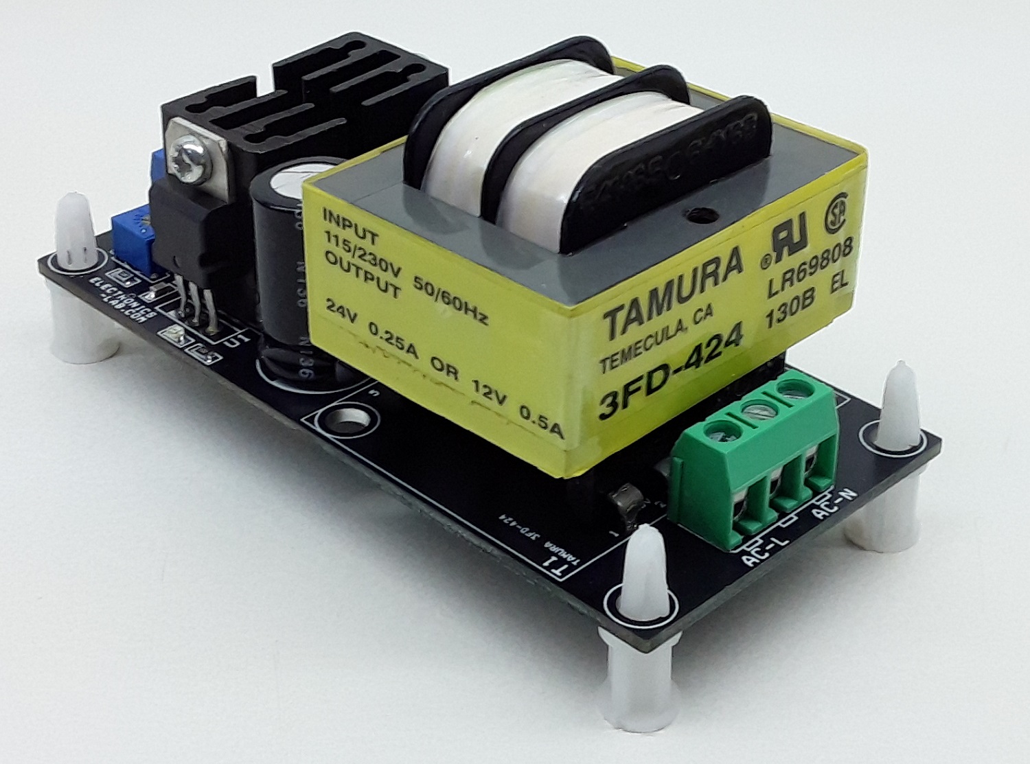
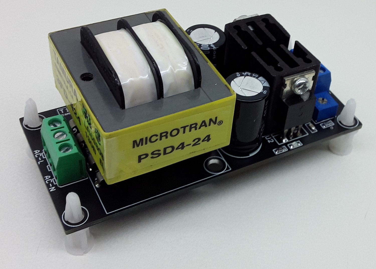
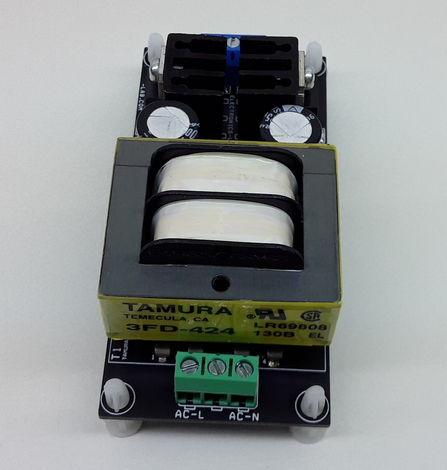
| 13 | 1 | T1 | TRANSFORMER 3FD-424 | TAMURA | DIGIKEY | MT2115-ND |
| 14 | 1 | U1 | LM317-ADJ TO 220 | ST | DIGIKEY | 497-1575-5-ND |
| 15 | 1 | U2 | LM337-ADJ TO 220 | ST | DIGIKEY | 497-1585-5-ND |
| 16 | 2 | HEATSINK -TO220 | AVID | DIGIKEY | HS106-ND | |
| 17 | 2 | M3 X 10MM SCREW AND NUT FOR TO220 HEATSINK/REGULATOR | IO AUDIO | DIGIKEY | 1937-IO-M3X10/M3HN-50-ND |
Connections
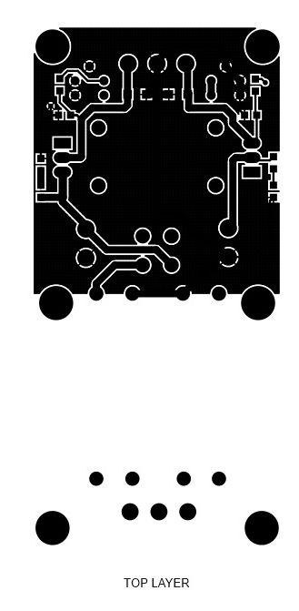
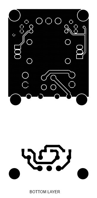
Gerber View
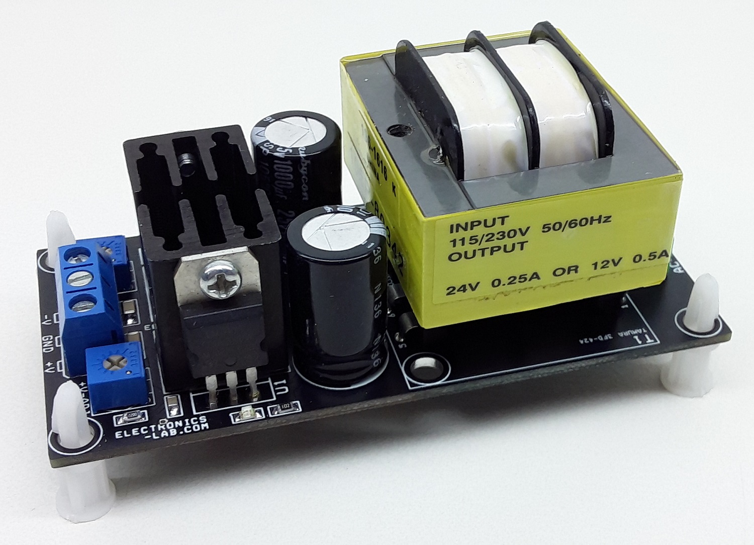
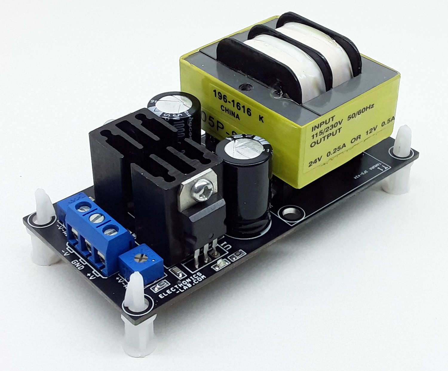
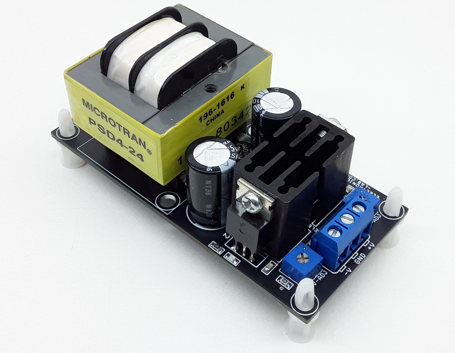
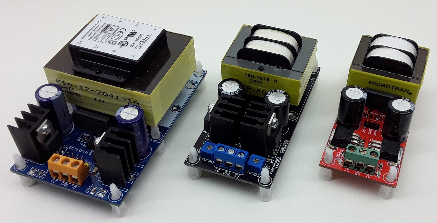
Photos
Video
LM317 Datasheet
Please follow and like us:
PCB

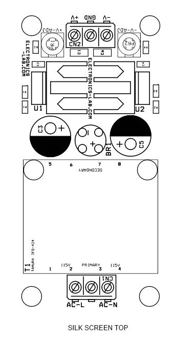


This is a nice project, good for powering op-amps and similar devices. You may want to correct the schematic symbol for T1. The datasheet says the phase indicators are on pins 1 and 3 on the primaries, and 5 and 7 on the secondaries. The way it is drawn is not correct. Functionally it works, obviously. If a shorter overall height is needed, one could use Triad Flap Pack series transformers.(Hammond low profile series)