Home Automation using NodeMCU (ESP8266) board
Home automation refers to the ability of your home to make its own decisions depending on environment conditions and give you the option to control it from a remote location. In one of our previous tutorial on the ESP8266 WiFi Module, we examined how NodeMCU or any of the other ESP8266 based boards can be used to build a web server through which all the GPIOs of the board can be controlled over WiFi.
Home automation refers to the ability of your home to make its own decisions depending on environment conditions and give you the option to control it from a remote location. In one of our previous tutorial on the ESP8266 WiFi Module, we examined how NodeMCU or any of the other ESP8266 based boards can be used to build a web server through which all the GPIOs of the board can be controlled over WiFi. Today, we are going to put that web server in use and control home appliances with it.
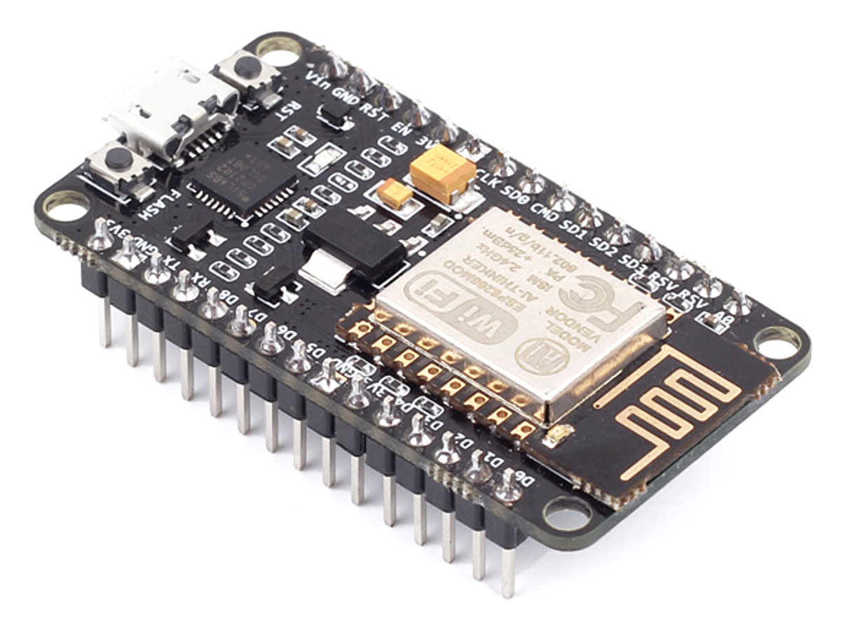
The heart of today’s project is the WiFi enabled board that needs no introduction; the ESP8266 based NodeMCU development board. It is an open source platform for developing WiFi based embedded systems and it is based on the popular ESP8266 WiFi Module, running the Lua based NodeMCU firmware. NodeMCU was born out of the desire to overcome the limitations associated with the first versions of the ESP8266 module which was not compatible with breadboards, it was difficult to power and even more difficult to program. The NodeMCU board is easy to use, low cost and that quickly endeared it to the heart of makers and it is one of the most popular boards today.
For today’s tutorial, we will add a 2-channel relay module to the ESP8266 board. The project flow involves the control of NodeMCU’s GPIOs from a webpage on any device connected on the same network as the board. The status of the GPIOs control the coils of the relays and that causes the relay to alternate between normally open (NO) and normally closed (NC) condition depending on the state of the GPIO, thus, effectively turning the connected appliance “ON” or “OFF”.
Required Components
The following components are required to build this project:
- NodeMCU (ESP8266-12E)
- 2-Channel Relay Module
- Breadboard
- Jumper Wire
For those who don’t have access to a relay module, you can use 2x single channel relay modules or single relays with the supporting transistor circuitry. For that purpose you will additionally need:
- 5v Relays (2)
- 2N2222 Transistor (2)
- 1N4007 Diode (2)
- 220 ohms resistor (2)
- 5V battery/PSU
Schematics
The schematics for this project is quite simple. Connect the components as shown in the diagram below.
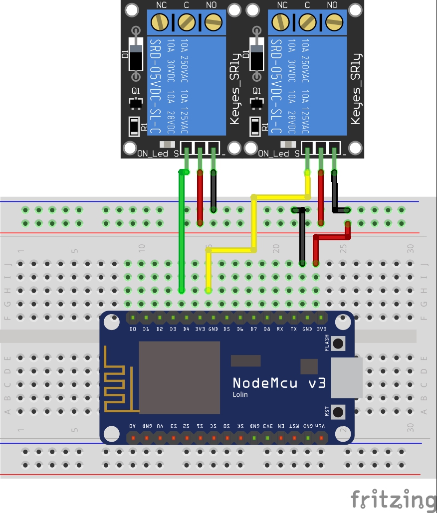
To make the connections easy to follow, here is a pin map of the connection between NodeMCU and the relay module.
NodeMCU – Relay Module
3.3V - VCC
GND - GND
D1 - D1
D2 - D2
D3 - D3
D4 - D4
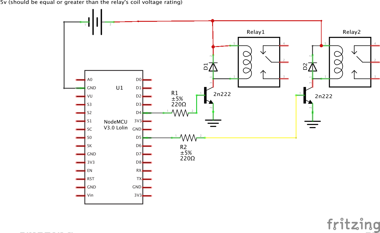
If you are using the ordinary relays without the module supporting circuit, connect the relays to the NodeMCU as shown below. Ensure the relay’s coils are rated 5v or change the 5v supply to match your relay’s rated coil voltage.
With the schematics done, we can then move forward to write the code for the project.
Code
One of the easiest way to program NodeMCU is via the Arduino IDE. This, however, requires setting up the Arduino IDE by installing the board support file for NodeMCU. If you are using the Arduino IDE to program the NodeMCU for the first time, you need to do this first before proceeding with this tutorial. Follow the detailed tutorial “Getting Started with the NodeMCU” to learn how to set up your Arduino IDE to program ESP8266 based boards.
The code for today’s tutorial is a modified version of the code from the last article “NodeMCU ESP8266 WebServer Tutorial“. The code is based on the ESP8266WiFi.h library which allows the easy use of WiFi functionalities of the board. It contains all we need to create or join a WiFi access point and also create a server and client which are all important for today’s project. The library comes attached with the NodeMCU board files for the Arduino, so there is no need to install it once the board files have been installed.
The code for today’s tutorial will enable us to control appliances connected to the GPIOs (via relays) of the NodeMCU board remotely.
To start with, we include the library that we will use for the project, which in this case, is the ESP8266WiFi.h library.
#include <ESP8266WiFi.h>
Next, we add the credentials of the WiFi access point to which the NodeMCU will be connected. Ensure the username and password are between the double quotes. We also specify the port through which the system will communicate and create a variable to hold requests.
// Add wifi access point credentiaals
const char* ssid     = "xxxxx";
const char* password = "xxxx";

WiFiServer server(80);// Set port to 80
Next, we declare the pins of the Nodemcu to which the relay pins are connected and create variables to hold the state of each relay.
// Declare the pins to which the appliances are connected via relays
int app1 = D1; //appliance 1
int app2 = D2; //appliance 2`
//you can add more more appliances below.

String app1state = "off";// state of appliance1
String app2state = "off";// state of appliance2
Next is the void setup() function. We start by initializing the serial monitor (as it will be used for debugging later on) and setting the pinModes of the pins to which the relays are connected as output. We then set the pins “LOW” to ensure the system starts at OFF state.
void setup() {
  Serial.begin(115200);
 // Set the pinmode of the pins to which the LEDs are connected and turn them low to prevent flunctuations
  pinMode(app1, OUTPUT);
  pinMode(app2, OUTPUT);
  digitalWrite(app1, LOW);
  digitalWrite(app2, LOW);
Next, we connect to the access point using the credentials provided as arguments to the WiFi.begin() function and we use the WiFi.status() function to check if connection was successful. The system will keep trying until the connection is successful.
//connect to access point
  WiFi.begin(ssid, password);
  Serial.print("Connecting to ");
  Serial.println(ssid);
  while (WiFi.status() != WL_CONNECTED) {
    delay(500);
    Serial.print(".");
  }
If the connection is successful, a text is printed on the serial monitor to indicate this, along with the IP address of the NodeMCU. This IP address becomes the web address for the server and should be entered on any web browser on the same network as the server so we are able to access it.
// Print local IP address and start web server
  Serial.println("");
  Serial.println("WiFi connected.");
  Serial.println("IP address: ");
  Serial.println(WiFi.localIP());// this will display the Ip address of the Pi which should be entered into your browse
}
Next, we start the server using the server.begin() function.
server.begin();
}
Next, we write the void loop() function. This is where a bulk of the work is done. We start by using the server.available() function to listen for incoming connections by clients (web browsers). When a client is available and connected, we read the client request and send a header as a response.
void loop(){
  WiFiClient client = server.available();   // Listen for incoming clients

  if (client) {                             // If a new client connects,
    String currentLine = "";                // make a String to hold incoming data from the client
    while (client.connected()) {            // loop while the client's connected
      if (client.available()) {             // if there's bytes to read from the client,
        char c = client.read();             // read a byte, then
        Serial.write(c);                    // print it out the serial monitor
        header += c;
        if (c == '\n') {                    // if the byte is a newline character
          // if the current line is blank, you got two newline characters in a row.
          // that's the end of the client HTTP request, so send a response:
          if (currentLine.length() == 0) {
            // HTTP headers always start with a response code (e.g. HTTP/1.1 200 OK)
            // and a content-type so the client knows what's coming, then a blank line:
            client.println("HTTP/1.1 200 OK");
            client.println("Content-type:text/html");
            client.println("Connection: close");
            client.println();
Next, the client’s request is examined to see if it indicates a button press on the web page. If it does, the state of the GPIO is changed accordingly to the request. If the request indicates “ON”, the pin is turned HIGH and the state variable is updated accordingly.
// turns the GPIOs on and off
           if (header.indexOf("GET /app1/on") >= 0) {
             Serial.println("App 1 on");
             app1state = "on";
             digitalWrite(app1, HIGH);
           } else if (header.indexOf("GET /app1/off") >= 0) {
             Serial.println("App 1 off");
             app1state = "off";
             digitalWrite(app1, LOW);
           } else if (header.indexOf("GET /app2/on") >= 0) {
             Serial.println("App 2 on");
             app2state = "on";
             digitalWrite(app2, HIGH);
           } else if (header.indexOf("GET /app2/off") >= 0) {
             Serial.println("App 2 off");
             app2state = "off";
             digitalWrite(app2, LOW);
           }
Next, we create the webpage that will be displayed and updated by the NodeMCU as the user interacts with it. The key function for this is the Client.println() function which is used to send HTML scripts line by line to the client.
We start by indicating that the next few texts to be printed are HTML lines as declaring by doctype.
client.println("<!DOCTYPE html><html>");
Next, we add the lines below to make webpage responsive irrespective of the browser being used.
client.println("<head><meta name=\"viewport\" content=\"width=device-width, initial-scale=1\">");
client.println("<link rel=\"icon\" href=\"data:,\">");
Next, some bits of CSS is sent to the client to make the web page look welcoming. You can edit this to add your own color, font style etc.
client.println("<style>html { font-family: Helvetica; display: inline-block; margin: 0px auto; text-align: center;}");
            client.println(".button { background-color: #195B6A; border: none; color: white; padding: 16px 40px;");
            client.println("text-decoration: none; font-size: 30px; margin: 2px; cursor: pointer;}");
            client.println(".button2 {background-color: #77878A;}</style></head>");
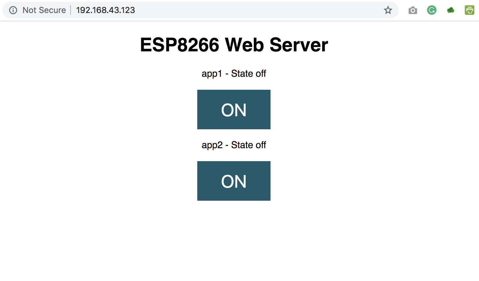
Next, the webpage header is sent followed by the buttons and the buttons are set to display the current state of the appliances. They will show OFF if the current state is ON and vice versa.
client.println("<body><h1>ESP8266 Web Server</h1>");

            // Display current state, and ON/OFF buttons for GPIO 5
            client.println("<p>app1 - State " + app1state + "</p>");
            // If Appliance 1 is off, it displays the ON button
            if (app1state == "off") {
              client.println("<p><a href=\"/app1/on\"><button class=\"button\">ON</button></a></p>");
            } else {
              client.println("<p><a href=\"/app1/off\"><button class=\"button button2\">OFF</button></a></p>");
            }

            // Display current state, and ON/OFF buttons for GPIO 4
            client.println("<p>app2 - State " + app2state + "</p>");
            // If Appliance 2 is off, it displays the ON button
            if (app2state == "off") {
              client.println("<p><a href=\"/app2/on\"><button class=\"button\">ON</button></a></p>");
            } else {
              client.println("<p><a href=\"/app2/off\"><button class=\"button button2\">OFF</button></a></p>");
            }
            client.println("</body></html>");

            // The HTTP response ends with another blank line
            client.println();
            // Break out of the while loop
            break;
          } else { // if you got a newline, then clear currentLine
            currentLine = "";
          }
        } else if (c != '\r') {  // if you got anything else but a carriage return character,
          currentLine += c;      // add it to the end of the currentLine
        }
      }
    }
Next, we close the connection and the flow goes back to the top.
 client.stop();
    Serial.println("Client disconnected.");
    Serial.println("");
  }
}
The complete code for the project is available below and also attached under the download section.
#include <ESP8266WiFi.h>

// Add wifi access point credentiaals
const char* ssid     = "xxxx";
const char* password = "xxxxx";

WiFiServer server(80);// Set port to 80


String header; // This storees the HTTP request

// Declare the pins to which the appliances are connected via relays
int app1 = D1; //appliance 1
int app2 = D2; //appliance 2`
//you can add more more appliances below.

String app1state = "off";// state of appliance1
String app2state = "off";// state of appliance2


void setup() {
  Serial.begin(115200);
 // Set the pinmode of the pins to which the LEDs are connected and turn them low to prevent flunctuations
  pinMode(app1, OUTPUT);
  pinMode(app2, OUTPUT);
  digitalWrite(app1, LOW);
  digitalWrite(app2, LOW);
  //connect to access point
  WiFi.begin(ssid, password);
  Serial.print("Connecting to ");
  Serial.println(ssid);
  while (WiFi.status() != WL_CONNECTED) {
    delay(500);
    Serial.print(".");
  }
  // Print local IP address and start web server
  Serial.println("");
  Serial.println("WiFi connected.");
  Serial.println("IP address: ");
  Serial.println(WiFi.localIP());// this will display the Ip address of the Pi which should be entered into your browser
  server.begin();
}

void loop(){
  WiFiClient client = server.available();   // Listen for incoming clients

  if (client) {                             // If a new client connects,
    String currentLine = "";                // make a String to hold incoming data from the client
    while (client.connected()) {            // loop while the client's connected
      if (client.available()) {             // if there's bytes to read from the client,
        char c = client.read();             // read a byte, then
        Serial.write(c);                    // print it out the serial monitor
        header += c;
        if (c == '\n') {                    // if the byte is a newline character
          // if the current line is blank, you got two newline characters in a row.
          // that's the end of the client HTTP request, so send a response:
          if (currentLine.length() == 0) {
            // HTTP headers always start with a response code (e.g. HTTP/1.1 200 OK)
            // and a content-type so the client knows what's coming, then a blank line:
            client.println("HTTP/1.1 200 OK");
            client.println("Content-type:text/html");
            client.println("Connection: close");
            client.println();

            // turns the GPIOs on and off
            if (header.indexOf("GET /app1/on") >= 0) {
              Serial.println("App 1 on");
              app1state = "on";
              digitalWrite(app1, HIGH);
            } else if (header.indexOf("GET /app1/off") >= 0) {
              Serial.println("App 1 off");
              app1state = "off";
              digitalWrite(app1, LOW);
            } else if (header.indexOf("GET /app2/on") >= 0) {
              Serial.println("App 2 on");
              app2state = "on";
              digitalWrite(app2, HIGH);
            } else if (header.indexOf("GET /app2/off") >= 0) {
              Serial.println("App 2 off");
              app2state = "off";
              digitalWrite(app2, LOW);
            }

            // Display the HTML web page
            client.println("<!DOCTYPE html><html>");
            client.println("<head><meta name=\"viewport\" content=\"width=device-width, initial-scale=1\">");
            client.println("<link rel=\"icon\" href=\"data:,\">");
            // CSS to style the on/off buttons
            // Feel free to change the background-color and font-size attributes to fit your preferences
            client.println("<style>html { font-family: Helvetica; display: inline-block; margin: 0px auto; text-align: center;}");
            client.println(".button { background-color: #195B6A; border: none; color: white; padding: 16px 40px;");
            client.println("text-decoration: none; font-size: 30px; margin: 2px; cursor: pointer;}");
            client.println(".button2 {background-color: #77878A;}</style></head>");

            // Web Page Heading
            client.println("<body><h1>ESP8266 Web Server</h1>");

            // Display current state, and ON/OFF buttons for GPIO 5
            client.println("<p>app1 - State " + app1state + "</p>");
            // If Appliance 1 is off, it displays the ON button
            if (app1state == "off") {
              client.println("<p><a href=\"/app1/on\"><button class=\"button\">ON</button></a></p>");
            } else {
              client.println("<p><a href=\"/app1/off\"><button class=\"button button2\">OFF</button></a></p>");
            }

            // Display current state, and ON/OFF buttons for GPIO 4
            client.println("<p>app2 - State " + app2state + "</p>");
            // If Appliance 2 is off, it displays the ON button
            if (app2state == "off") {
              client.println("<p><a href=\"/app2/on\"><button class=\"button\">ON</button></a></p>");
            } else {
              client.println("<p><a href=\"/app2/off\"><button class=\"button button2\">OFF</button></a></p>");
            }
            client.println("</body></html>");

            // The HTTP response ends with another blank line
            client.println();
            // Break out of the while loop
            break;
          } else { // if you got a newline, then clear currentLine
            currentLine = "";
          }
        } else if (c != '\r') {  // if you got anything else but a carriage return character,
          currentLine += c;      // add it to the end of the currentLine
        }
      }
    }
    // Clear the header variable
    header = "";
    // Close the connection
    client.stop();
    Serial.println("Client disconnected.");
    Serial.println("");
  }
}
Demo
Upload the code to the NodeMCU. Ensure everything is connected as described under the schematics section. After uploading the code, you should see the IP address of your web server displayed in the serial monitor as shown below.
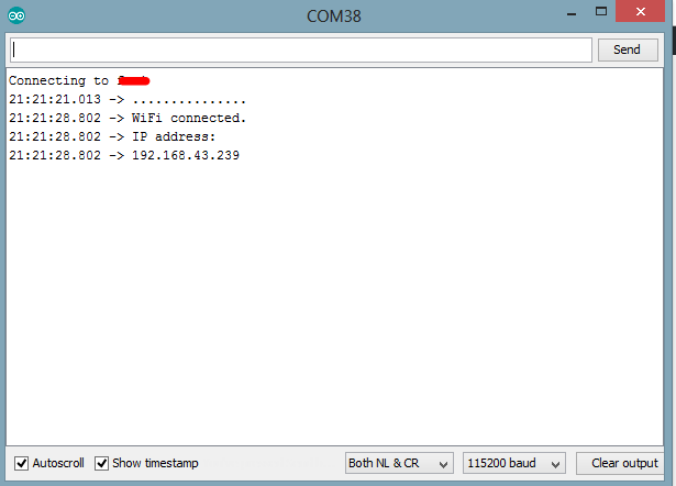
Copy the IP address and paste it in a web browser on any device (Mobile or PC) connected to the same network as the NodeMCU. You should see the web page and be able to toggle the connected appliances by clicking the buttons.
That’s it for this tutorial. Thanks for reading.
As mentioned above, this tutorial could serve as a building block for more complex web servers and IoT solutions. What will you build?
If you have any question about today’s tutorial, please feel free to share via the comment section.
Till Next time!
how to make it work both onlinne and offline by controlling it remotely
What are the needed changes to display the webpage on a website to access it from any place(not only local network)
To be able to access the webpage from anywhere, you can do a number of things including;
1. Port forwarding of the router to which the ESP WIFi is connected (this may have a lot of security risks).
2. get a domain name and hosting and host the webpage on it.
3. Use cloud services like Adafruit.io or the Arduino IoT Cloud which comes with an app and desktop dashboard.
Don’t working when accesing it from WAN. Any solutions?
bro your pins in circuit diagram and code doesnt match in code its D1 and D2 but in ckt its D4 and GND
D4 and D5. Feel free to change accordingly. Fritzing makes things difficult at times. but you can check the schematics(not the breadboard connections) to get a better idea.
Hi nice project i have tested it and working , but there is an issue that is: If my get disconnected from the network and when i rconnect it with the network the ESP did’t respond, untill i reset the ESP. Did you observed this if so, Any solution?
I changed the code for three relays but in serial monitor it shows no nodemcu found. what can be the problem? tell me what coding parts should be changed.
Hi
There isn’t such “2N222” transistor, google it and no result.
Is that “2N2222” ?
Yes, this was a typo error, thanks for noticing.
thanks
and last question 😉
when I run esp8266, it show me “farylink” open wireless AP.
how can I disable it?
hey there! Can i give id and password of my mobile’s wifi ?
because I don’t have wifi installed at my house can I use mobile’s Hotspot to do so??
Plz reply 🙂
Yes you can
how to make it for4 appliances, i hv tried bt 2 more buttons display on webpage bt not responding.
i could see the code has reverse behaviour, when ON is clicked LED goes off and vice versa. But the expecation is that it should ON when click on