

Isolated RS485/RS422 Transceiver with Integrated DC-DC Converter
- Rajkumar Sharma
- 112 Views
- medium
- Tested
- SKU: EL143683
- Quote Now
- 0 Likes

The project presented here is a galvanically isolated differential line transceiver with a built-in isolated DC-DC converter for TIA/EIA RS-485 and RS-422 applications. Both signal and power paths are isolated per UL1577 and are qualified for reinforced isolation per VDE, CSA, and CQC. The low-emissions, isolated DC/DC converter ensures the final system is capable of meeting CISPR 32 radiated emissions limit lines with just two ferrites’ beads. The project is ideal for long-distance communications. Isolation breaks the ground loop between the communicating nodes, allowing for a much larger common-mode voltage range.
The project supports a maximum data rate of 12 Mbps. It can operate from a single supply voltage of 3V to 5.5V by connecting VC and 5V on PCB. If lower logic levels are required, these devices support a 1.71V to 5.5V logic supply (VIO) that can be independent from the power converter supply (VDD) of 3V to 5.5V.
Features
- Power Supply Logic 1.71 V to 5.5V DC
- Power Converter Supply 3V to 5.5V
- For Single Supply Operation Supply Input Range 3V to 5.5V (Combined DC-DC Input and Logic Power Input)
- Power Converter Output Isolated (Output) Side 3.3V (Can be Changed to 5V)
- Integrated low-emissions DC-DC converter with low-emissions, low-noise
- RS-485 with PROFIBUS Compatibility – Open, Short, and Idle Bus Failsafe
- 1/8 Unit Load: Up to 256 Nodes on Bus
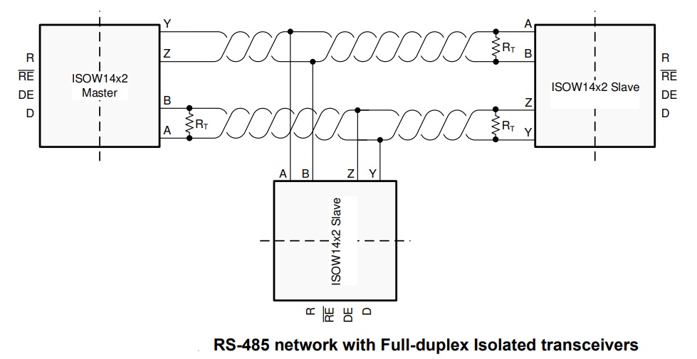
- Project Supports Full-Duplex, It Can also Be Used for Half-Duplex
- Glitch-free Power Up Down
- Current Limit and Thermal Shutdown
- 4 x 3 mm Mounting Holes
- PCB Dimensions 56.04 x 31.12 mm
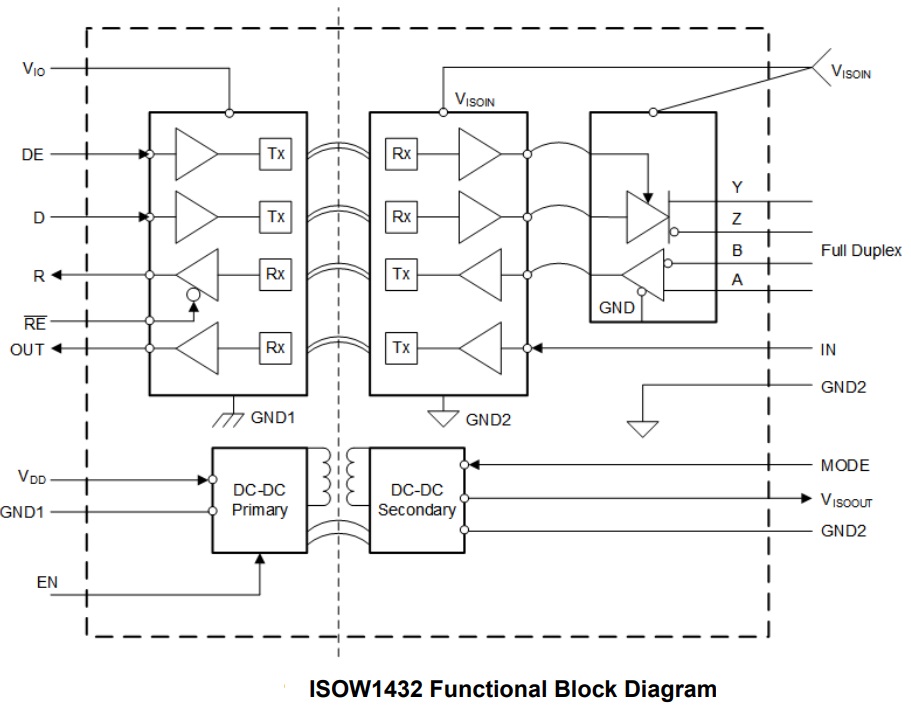
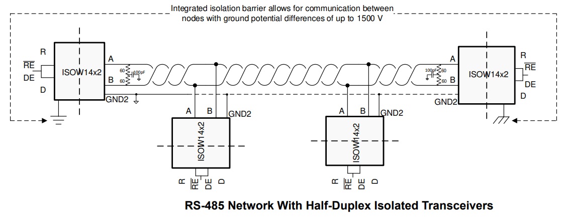
In a typical RS-485 network, multiple nodes may be connected on the bus and the distance of communicating nodes can be as far as 4000-5000 feet. While communicating at such large distances, a usual common mode of non-isolated RS-485 transceiver is not sufficient. ISOW1432 has an integrated isolation barrier with up to 1500 Vpk working voltage rating. Isolation breaks the ground loop between the communicating nodes and allows for data transfer in the presence of large ground potential differences. These devices have a higher typical differential output voltage (VOD) than traditional transceivers for better noise immunity. A minimum differential output voltage of 2.1 V is specified when VISOIN is configured for 5 V supply which meets the requirements for PROFIBUS applications. Only external bypass capacitors are needed to fully realize an isolated RS-485 port. This family of devices is also suitable for very high voltage applications, where power transformers for discrete isolated supply meeting the required isolation specifications are bulky and expensive. Though the device family is full-duplex, it can also be used for half-duplex applications by connecting driver output (Y, Z) to receiver input (A, B) on PCB this helps to reduce cabling Cost.
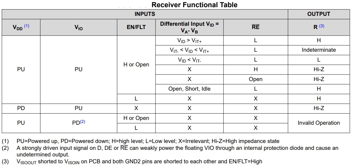
Failsafe Receiver
The differential receiver of the ISOW1432 devices has failsafe protection from invalid bus states caused by:
- Open bus conditions such as a broken cable or a disconnected connector
- Shorted bus conditions such as insulation breakdown of a cable that shorts the twisted-pair
- Idle bus conditions that occur when no driver on the bus is actively driving
Glitch-Free Power Up and Power Down
Communication on the bus that already exists between a master node and slave node in an RS-485 network must not be disturbed when a new node is swapped in or out of the network. No glitches on the bus should occur when the device is:
- Hot plugged into the network in an unpowered state
- Hot plugged into the network in a powered state and disabled state
- Powered up or powered down in a disabled state when already connected to the bus
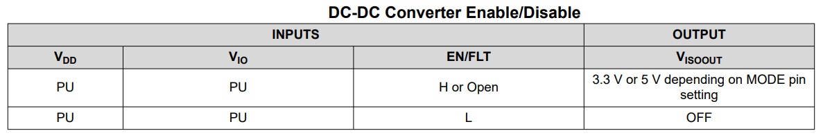
Enable/Fault
The first feature is an Enable/Fault protection feature. This EN/FLT pin can be used as either an input pin to enable or disable the integrated DC-DC power converter or as an output pin which works as an alert signal if the power converter is not operating properly. In the /Fault use case, a fault is reported if VDD > 7 V, VDD < 2.5 V, or if the junction temperature >170°C. When a fault is detected, this pin will go low, disabling the DC-DC converter to prevent any damage
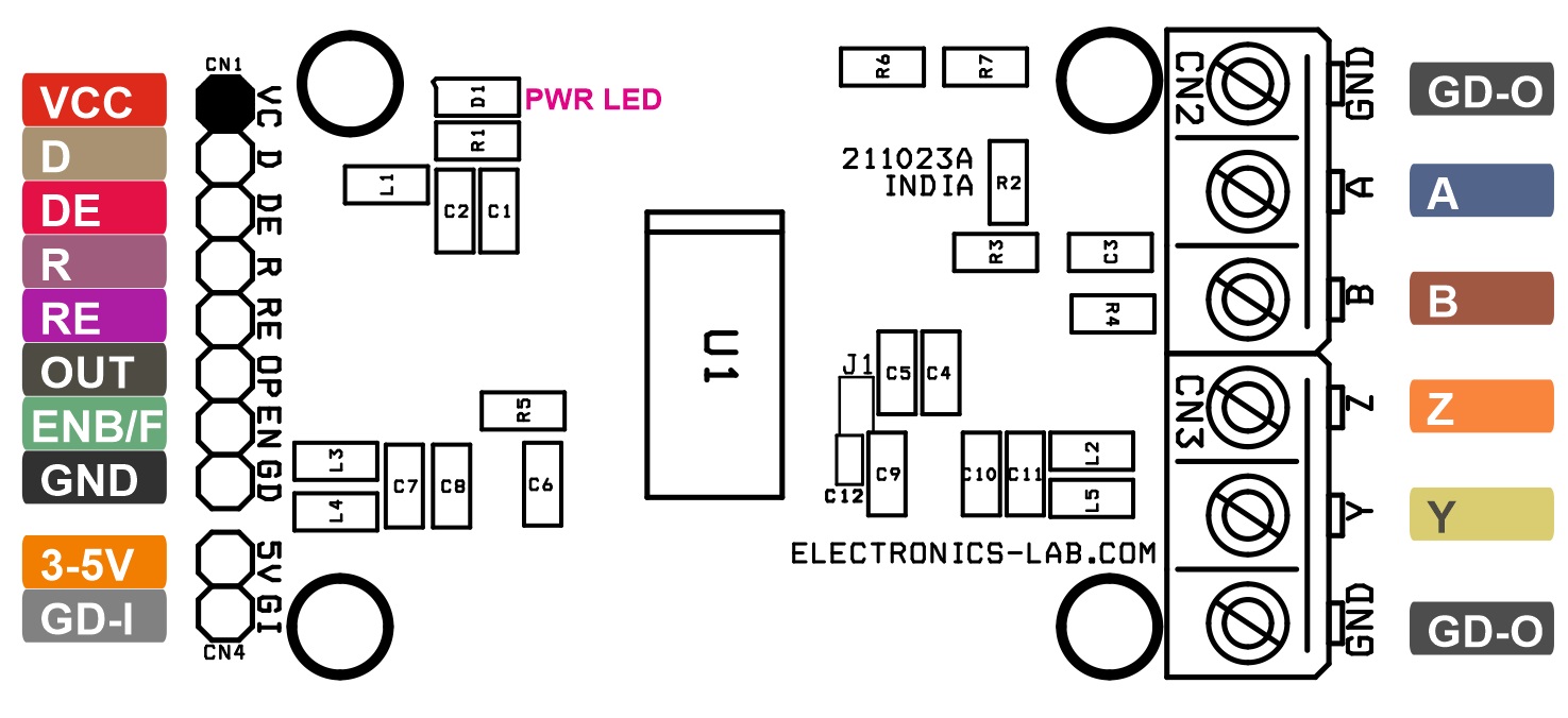
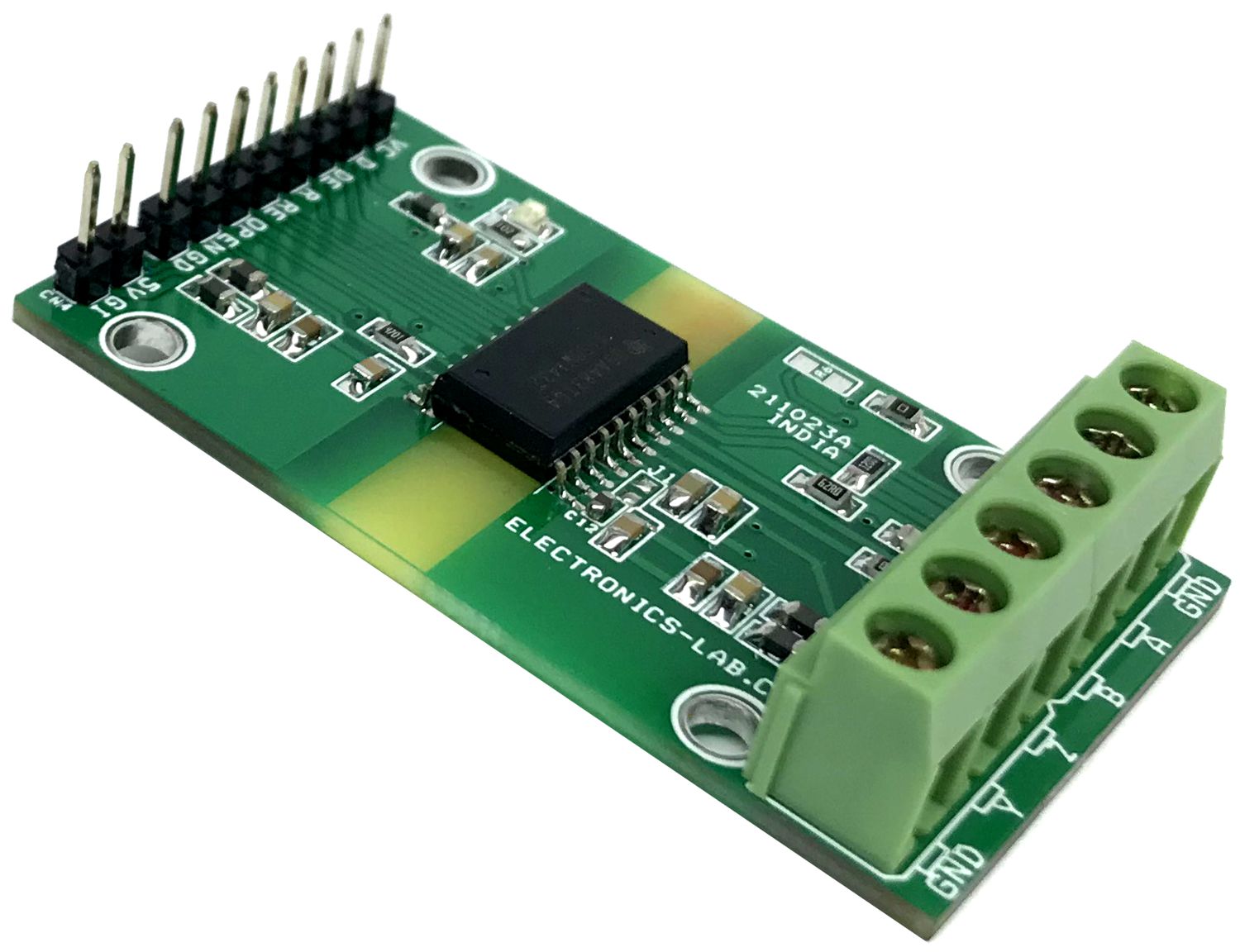
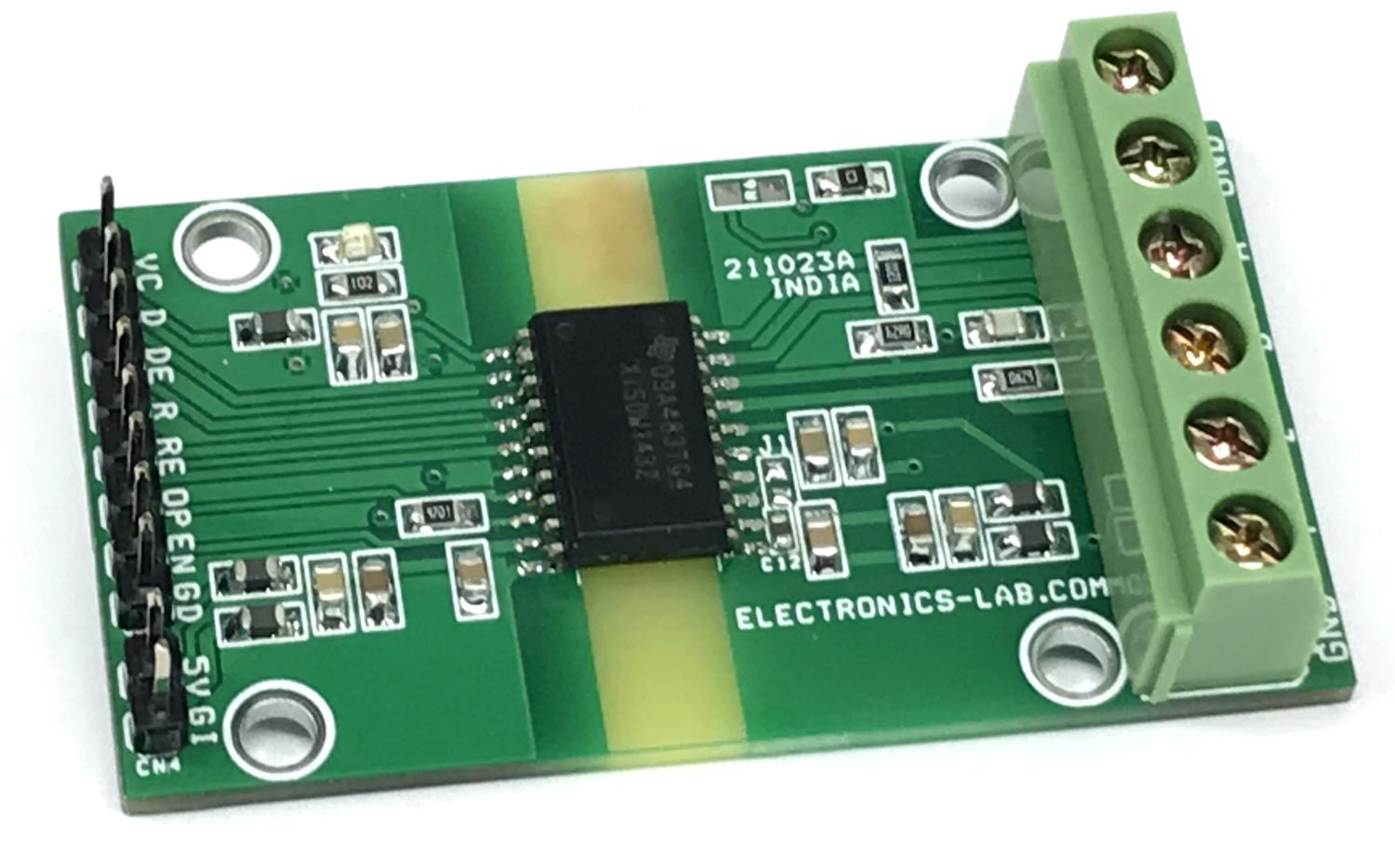
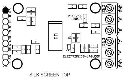
Connections
- CN1:
- Pin 1 = VCC 1.71V to 5.5V,
- Pin 2 = Data In
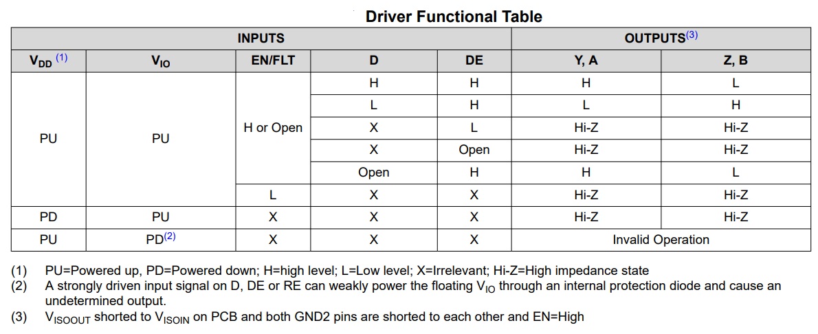
- Pin 3 = DE Driver Enable, if pin is floating, driver is disabled (internal pull-down resistor)
- Pin 4 = R Received data output
- Pin 5 = Receiver Enable, if pin is floating, receiver buffer is disabled (internal pull-up resistor)
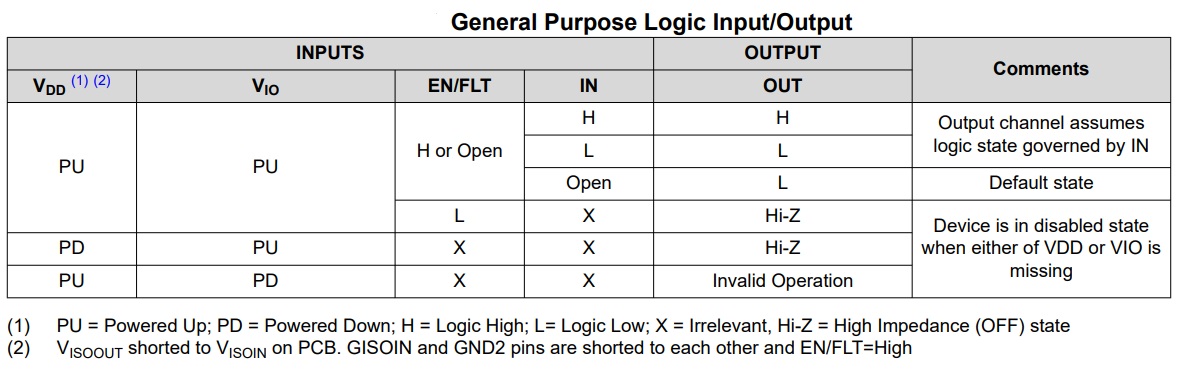
- Pin 6 = OP General purpose logic output
- Pin 7 = EN/FLT Multi-function power converter enable input pin or fault output pin. Can only be used as either an input pin or an output pin
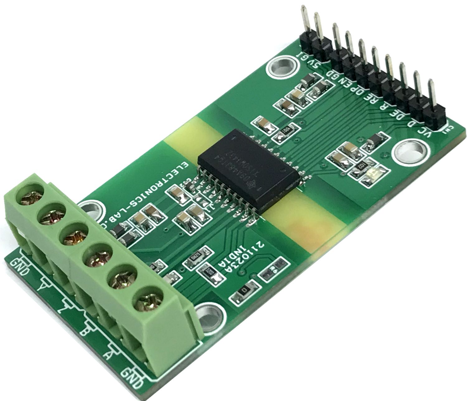
- CN2: Pin 1 = GND-Output, Pin 2 = A, Pin 3 = B
- CN3: Pin 1 = Z, Pin 2 = Y, Pin 3 = GND-Output
- CN4: Pin 1 = 3-5V DC Input for DC-DC Converter, Pin 2 = GND-Input
- D1: Power LED
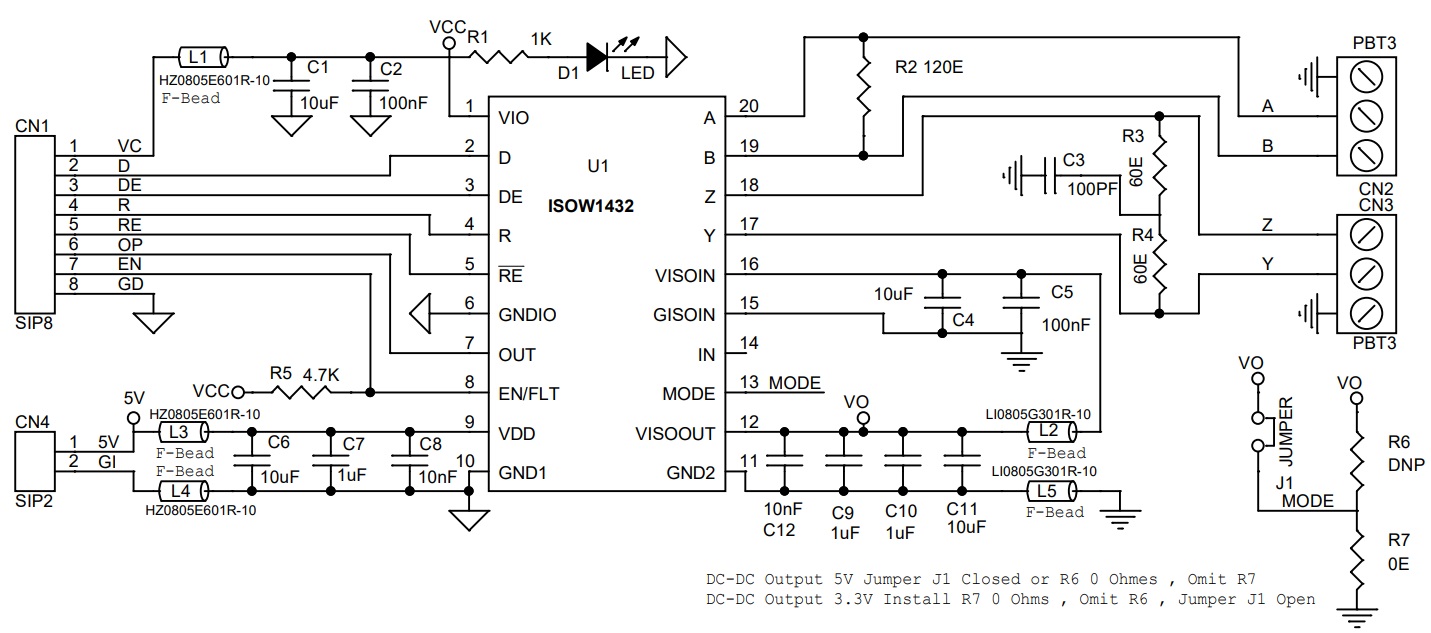
Schematic
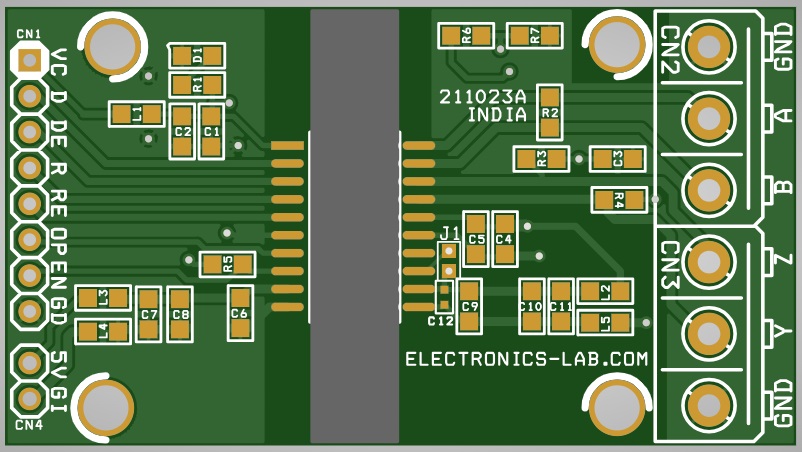
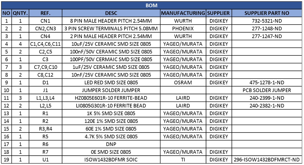
Parts List
| NO | QNTY. | REF. | DESC | MANUFACTURING | SUPPLIER | SUPPLIER PART NO |
|---|---|---|---|---|---|---|
| 1 | 1 | CN1 | 8 PIN MALE HEADER PITCH 2.54MM | WURTH | DIGIKEY | 732-5321-ND |
| 2 | 2 | CN2,CN3 | 3 PIN SCREW TERMINALS PITCH 5.08MM | PHOENIX | DIGIKEY | 277-1248-ND |
| 3 | 1 | CN4 | 2 PIN MALE HEADER PITCH 2.54MM | WURTH | DIGIKEY | 277-1247-ND |
| 4 | 4 | C1,C4,C6,C11 | 10uF/25V CERAMIC SMD SIZE 0805 | YAGEO/MURATA | DIGIKEY | |
| 5 | 2 | C2,C5 | 100nF/50V CERAMIC SMD SIZE 0805 | YAGEO/MURATA | DIGIKEY | |
| 6 | 1 | C3 | 100PF/50V CERMAIC SMD SIZE 0805 | YAGEO/MURATA | DIGIKEY | |
| 7 | 3 | C7,C9,C10 | 1uF/25V CERAMIC SMD SIZE 0805 | YAGEO/MURATA | DIGIKEY | |
| 8 | 2 | C8,C12 | 10nF/25V CERAMIC SMD SIZE 0805 | YAGEO/MURATA | DIGIKEY | |
| 9 | 1 | D1 | LED RED SMD SIZE 0805 | OSRAM | DIGIKEY | 475-1278-1-ND |
| 10 | 1 | J1 | JUMPER SOLDER JUMPER | PCB SOLDER JUMPER | ||
| 11 | 3 | L1,L3,L4 | HZ0805E601R-10 FERRITE-BEAD | LAIRD | DIGIKEY | 240-2399-1-ND |
| 12 | 2 | L2,L5 | LI0805G301R-10 FERRITE BEAD | LAIRD | DIGIKEY | 240-2382-1-ND |
| 13 | 1 | R1 | 1K 5% SMD SIZE 0805 | YAGEO/MURATA | DIGIKEY | |
| 14 | 1 | R2 | 120E 1% SMD SIZE 0805 | YAGEO/MURATA | DIGIKEY | |
| 15 | 2 | R3,R4 | 60E 1% SMD SIZE 0805 | YAGEO/MURATA | DIGIKEY | |
| 16 | 1 | R5 | 4.7K 5% SMD SIZE 0805 | YAGEO/MURATA | DIGIKEY | |
| 17 | 1 | R6 | DNP | |||
| 18 | 1 | R7 | 0E SMD SIZE 0805 | YAGEO/MURATA | DIGIKEY | |
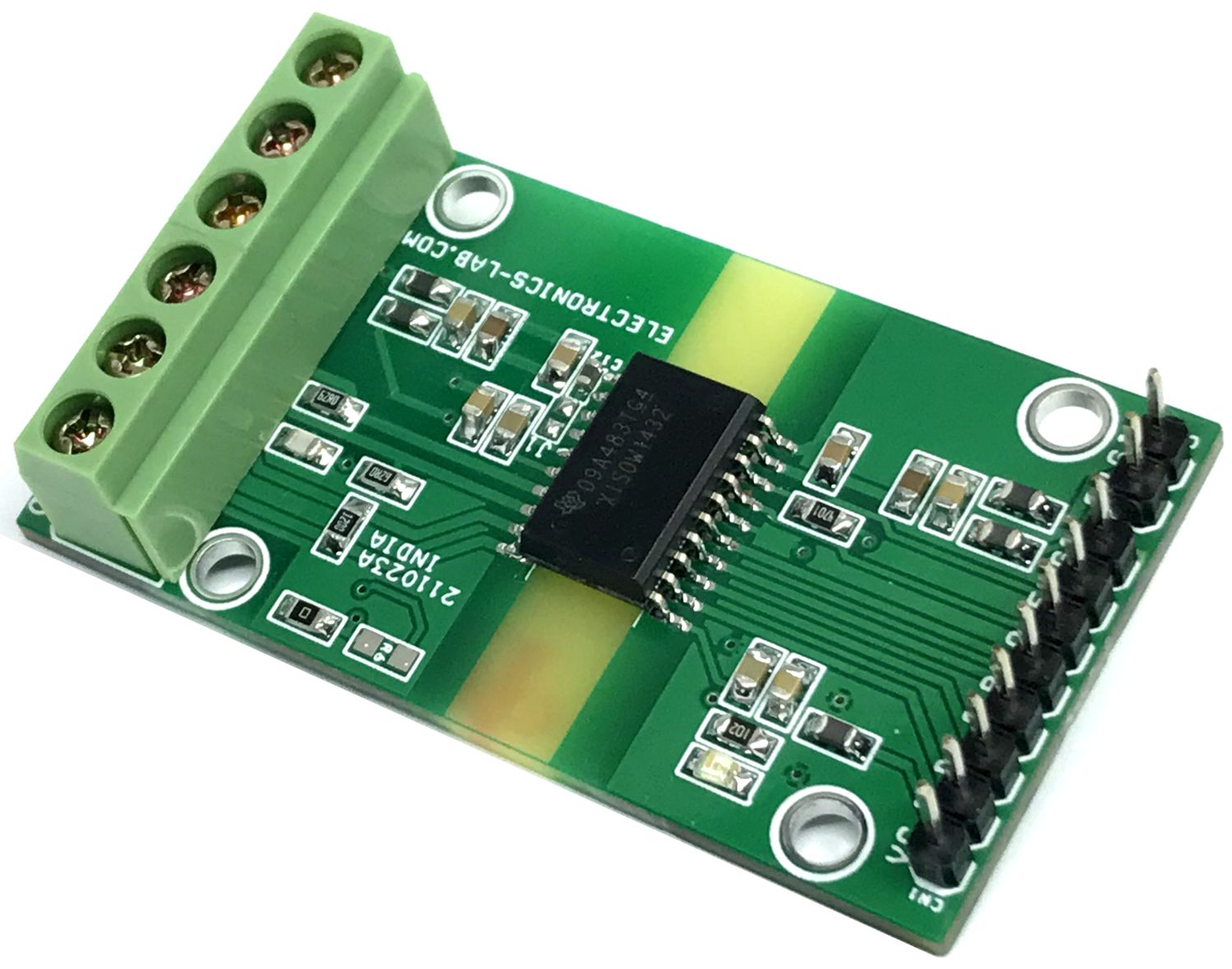
| 19 | 1 | U1 | ISOW1432BDFMR SOIC | TI | DIGIKEY | 296-ISOW1432BDFMRCT-ND |
Connections
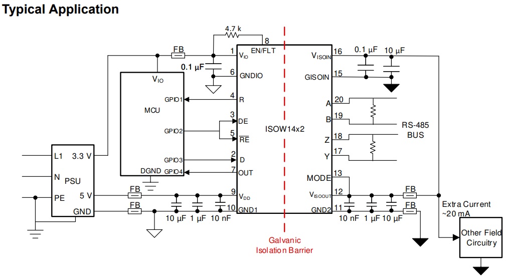
Typical Application
Function Tables
Diagrams
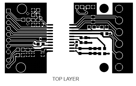
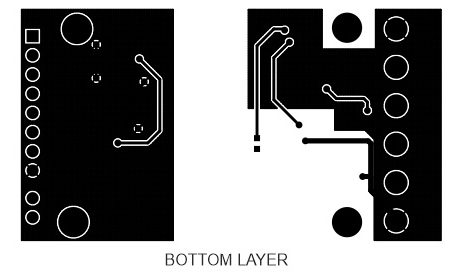
Gerber View
Photos
Video
ISOW1432 Datasheet
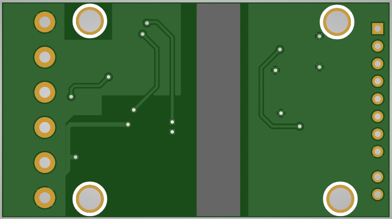
PCB


")