Isolator for SPI Interface with Inbuilt DC-DC Converter
This simple, compact solution is ideal for isolated SPI data requiring communication across different ground potentials often found in Industrial PLCs (programmable logic controllers) and Instrumentation and data acquisition systems. Serial Peripheral Interface (SPI) is a protocol that is commonly used for communication between microcontrollers and peripheral ICs such as sensors, ADCs, DACs, and others.
This simple, compact solution is ideal for isolated SPI data requiring communication across different ground potentials often found in Industrial PLCs (programmable logic controllers) and Instrumentation and data acquisition systems. Serial Peripheral Interface (SPI) is a protocol that is commonly used for communication between microcontrollers and peripheral ICs such as sensors, ADCs, DACs, and others. The project is based on an ISOW7741 quad-channel digital isolator with an integrated DC-DC converter. For many industrial control applications, the communications pathway between the microcontroller and the I/O module devices must be isolated. Isolation helps to minimize noise and ground loop issues and also protects expensive control units (MCUs or FPGAs) and equipment operators. This module is the solution to all these problems and the inbuilt DC-DC converter is a great advantage that powers the output side of the circuitry and thus the project can work with a single supply. The DC-DC converter output can be used to power the peripherals device maximum load up to 100mA with 5VDC input.
Features
- Power Supply Logic 1.71V to 5.5V
- Power Supply DC-DC Converter 3V to 5.5V
- Single Supply Operation 3V to 5.5V (Logic Power + DC-DC Power)
- Project Supports 3.3V and 5V Interface
- Maximum Load Data Channel 15mA (I/O)
- DC-DC Converter Output Available for Peripherals Load Up to 100mA with 5V Supply DC-DC Converter
- 100 Mbps Data Rate
- Isolation Ratings 5000V-RMS
- Independent power supply for channel isolator & power converter
- ±8 kV IEC 61000-4-2 contact discharge protection across isolation barrier
- Integrated DC-DC converter with low-emissions, low-noise
- Emission optimized to meet CISPR 32 and EN 55032 Class B with >5 dB margin on 2-layer board
- Low-frequency power converter at 25 MHz enabling low noise performance
- Low output ripple: 24 mV
- High-efficiency output power
- Efficiency at max load: 46%
- Up to 0.55-W output power
- On Board Power LED (Logic Power)
- Header Connectors for easy connections
- PCB Dimensions 50.17 x 21.75 mm
DC-DC Converter Input and Output
- DC-DC Converter Power Supply 5V DC =Output 5V DC, Load Current 110mA
- DC-DC Converter Power Supply 5V DC =Output 3.3V DC, Load Current 140mA
- DC-DC Converter Power Supply 3.3V DC =Output 3.3V DC, Load Current 60mA
Output Power (DC-DC Converter)
The integrated isolated DC-DC converter uses advanced circuit and on-chip layout techniques to reduce radiated emissions and achieve up to 46% typical efficiency. The integrated transformer uses thin film polymer as the insulation barrier. The output voltage of the power converter can be controlled to 3.3 V or 5 V using VSEL pin. Read Note 2 for output voltage selection.
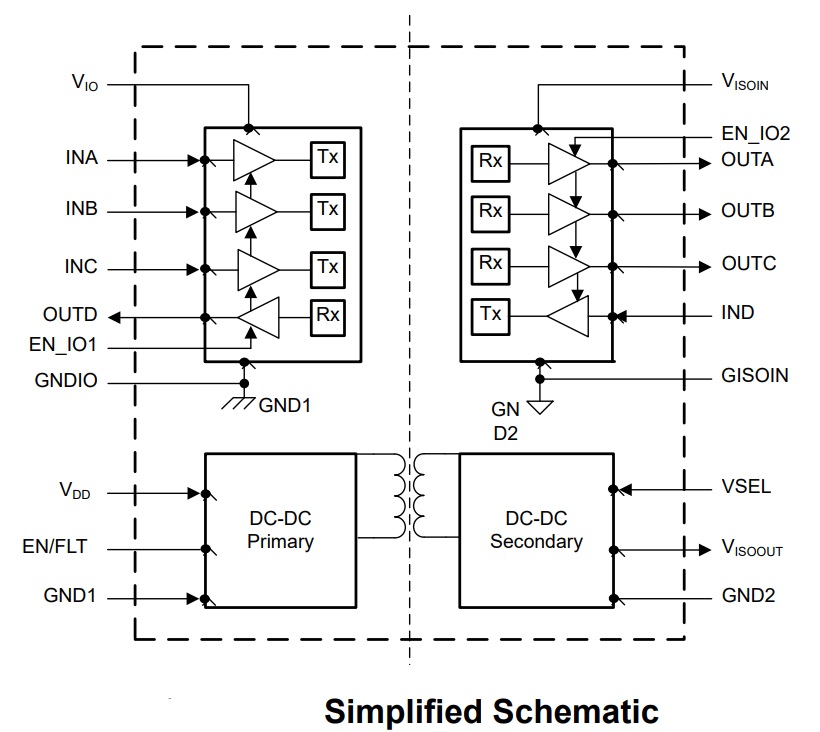
4 Channel Input/Outputs
The project has four high-speed three forward and one reverse direction channels. The first three forward channels can be used, for CS (Chip Select) CLK, MI/SO, and the fourth reverse channel for MO/SI (the slash indicates the connection of the particular input and output channel across the isolator)
The device ISOW7741 is high-performance, quad channel digital isolator with integrated DC-DC converter. Typically, digital isolators require two power supplies isolated from each other to power up both sides of device. Due to the integrated DC-DC converter in the device, the isolated supply is generated inside the device that can be used to power isolated side of the device and peripherals on isolated side, thus saving board space. The device uses single-ended CMOS-logic switching technology.
SPI Signals
- SCLK: The synchronous clock used by all devices. The master drives this clock and the slaves receive it. Note that SCLK can be gated and need not be driven between SPI transactions.
- MOSI: Master out, slave in. Also called DO on the Master or DI on the slave. This is the main data line driven by the master to all slaves on the SPI bus. Only the selected slave clocks data from MOSI.
- MISO: Master in, slave out. Also called DI on the Master and DO on the Slave. This is the main data line driven by the selected slave to the master. Only the selected slave may drive this signal.
- CS: Chip Select, this signal is unique to each slave. When active (generally low) the selected slave must drive MISO based on SCLK transitions.
ISOW7741 Chip Overview
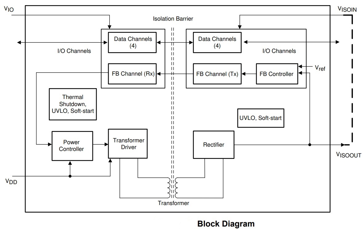
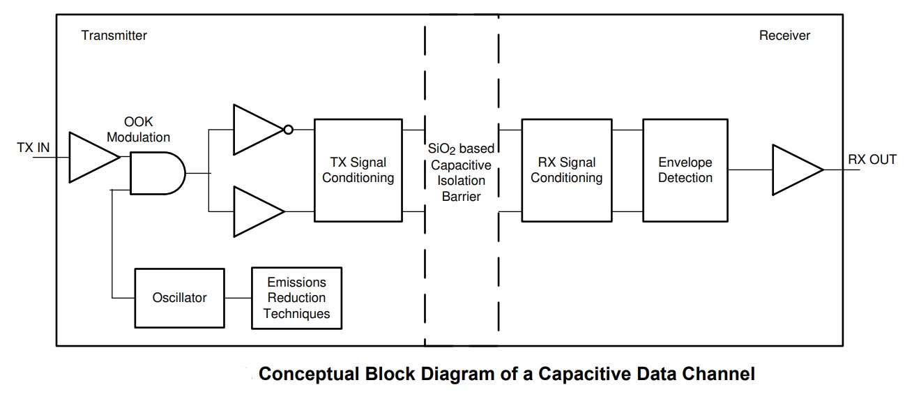
The ISOW7741 device is a galvanically-isolated quad- channel digital isolator with an integrated high-efficiency, low emissions power converter. The integrated DC-DC converter provides up to 500 mW of isolated power, eliminating the need for a separate isolated power supply in space-constrained isolated designs. The high efficiency of the power converter allows for operation at a wide operating ambient temperature range of –40°C to +125°C. This device provides improved emissions performance, allowing for simplified board design and has provisions for ferrite beads to further attenuate emissions. The ISOW7741 has been designed with enhanced protection features in mind, including soft-start to limit inrush current, over-voltage and under-voltage lock out, fault detection on the EN_DC DC pin, overload and short-circuit protection, and thermal shutdown. The ISOW7741 device provides high electromagnetic immunity while isolating CMOS or LVCMOS digital I/Os. The signal-isolation channel has a logic input and output buffer separated by a double capacitive silicon dioxide (SiO2) insulation barrier, whereas, power isolation uses on-chip transformers separated by thin film polymer as insulating material. The ISOW7741 can operate from a single supply voltage of 3 V to 5.5 V by connecting VIO and VDD together on PCB. If lower logic levels are required, these devices support 1.71 V to 5.5 V logic supply (VIO) that can be independent from the power converter supply (VDD) of 3 V to 5.5 V. VISOIN and VISOOUT needs to be connected on board with either a ferrite bead or fed through a LDO.
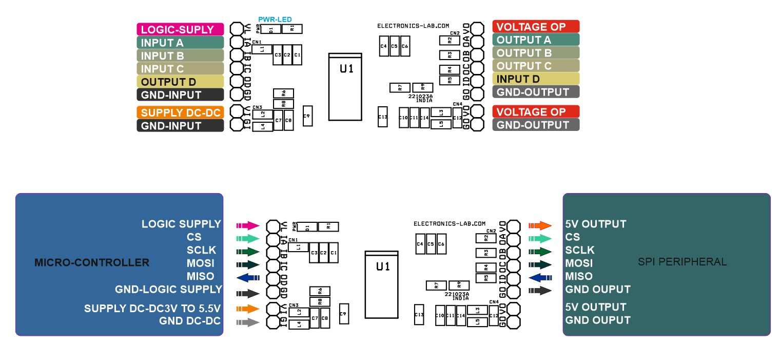
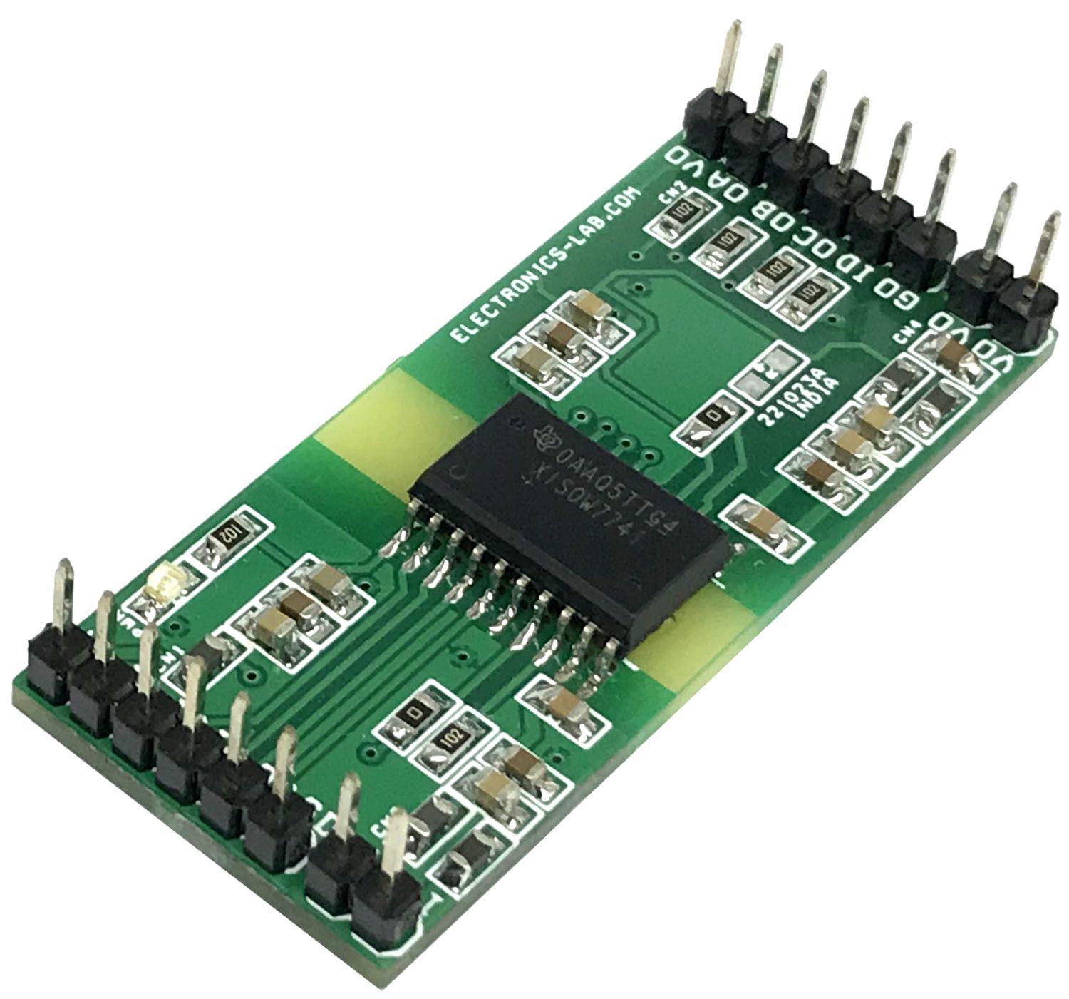
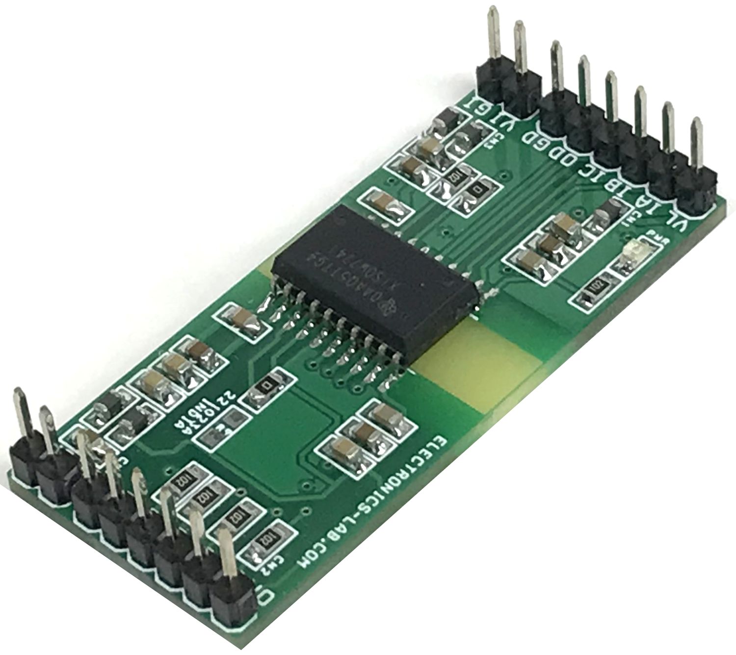
Connections
- CN1: Pin 1 Logic Supply 1.71V to 5.5V, Pin 2 Input A, Pin 3 Input B, Pin 4 Input C, Pin 5 Output D, Pin 6 GND
- CN2: Pin 1 DC-DC Converter Output, Pin 2 Output A, Pin 3 Output B, Pin 4 Output C, Pin 5 Input D, Pin 6 GND-Output
- CN3: Pin 1 Input Supply for DC-DC Converter 3V to 5.5V DC, Pin 2 GND-Input
- CN4: Pin 1 +DC-DC Output for Peripherals, Pin 2 = GND-Output
- D1: Power LED Logic Supply
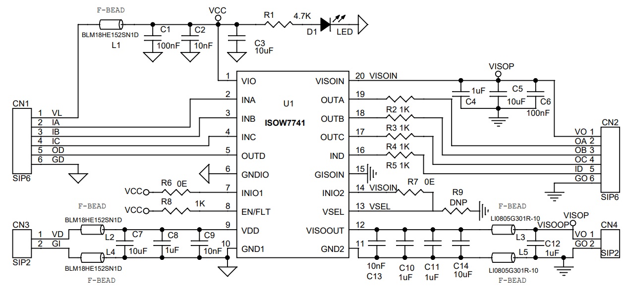
Schematic
Parts List
| NO | QNTY | REF | DESC | MANUFACTURER | SUPPLIER | SUPPLIER PART NO |
|---|---|---|---|---|---|---|
| 1 | 2 | CN1,CN2 | 6 PIN MALE HEADER PITCH 2.54MM | WURTH | DIGIKEY | 732-5319-ND |
| 2 | 2 | CN3,CN4 | 2 PIN MALE HEADER PITCH 2.54MM | WURTH | DIGIKEY | 732-5315-ND |
| 3 | 2 | C1,C6 | 100nF/50V CERAMIC SMD SIZE 0805 | YAGEO/MURATA | DIGIKEY | |
| 4 | 3 | C2,C9,C13 | 10nF/50V CERAMIC SMD SIZE 0805 | YAGEO/MURATA | DIGIKEY | |
| 5 | 4 | C3,C5,C7,C14 | 10uF/25V CERAMIC SMD SIZE 0805 | YAGEO/MURATA | DIGIKEY | |
| 6 | 5 | C4,C8,C10,C11,C12 | 1uF/25V CERAMIC SMD SIZE 0805 | YAGEO/MURATA | DIGIKEY | |
| 7 | 1 | D1 | LED RED SMD SIZE 0805 | OSRAM | DIGIKEY | 475-1278-1-ND |
| 8 | 3 | L1,L2,L4 | BLM18HE152SN1D | MURATA | DIGIKEY | 240-2398-1-ND |
| 9 | 2 | L3,L5 | LI0805G301R-10 | LAIRD SIGNAL | DIGIKEY | 240-2382-1-ND |
| 10 | 1 | R1 | 4.7K 5% SMD SIZE 0805 | YAGEO/MURATA | DIGIKEY | |
| 11 | 5 | R2,R3,R4,R5,R8 | 1K 5% SMD SIZE 0805 | YAGEO/MURATA | DIGIKEY | |
| 12 | 2 | R6,R7 | 0E SMD SIZE 0805 | YAGEO/MURATA | DIGIKEY | |
| 13 | 1 | R9 | DNP | |||
| 14 | 1 | U1 | ISOW7741FDFMR | TI | DIGIKEY | 296-ISOW7741FDFMRCT-ND |
Connections
Block Diagram
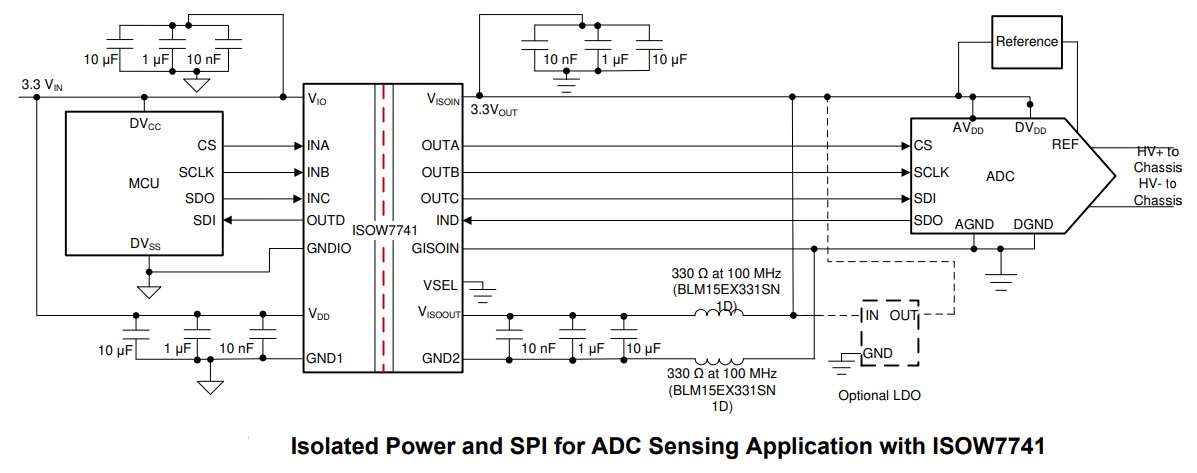
Typical Application
Gerber View
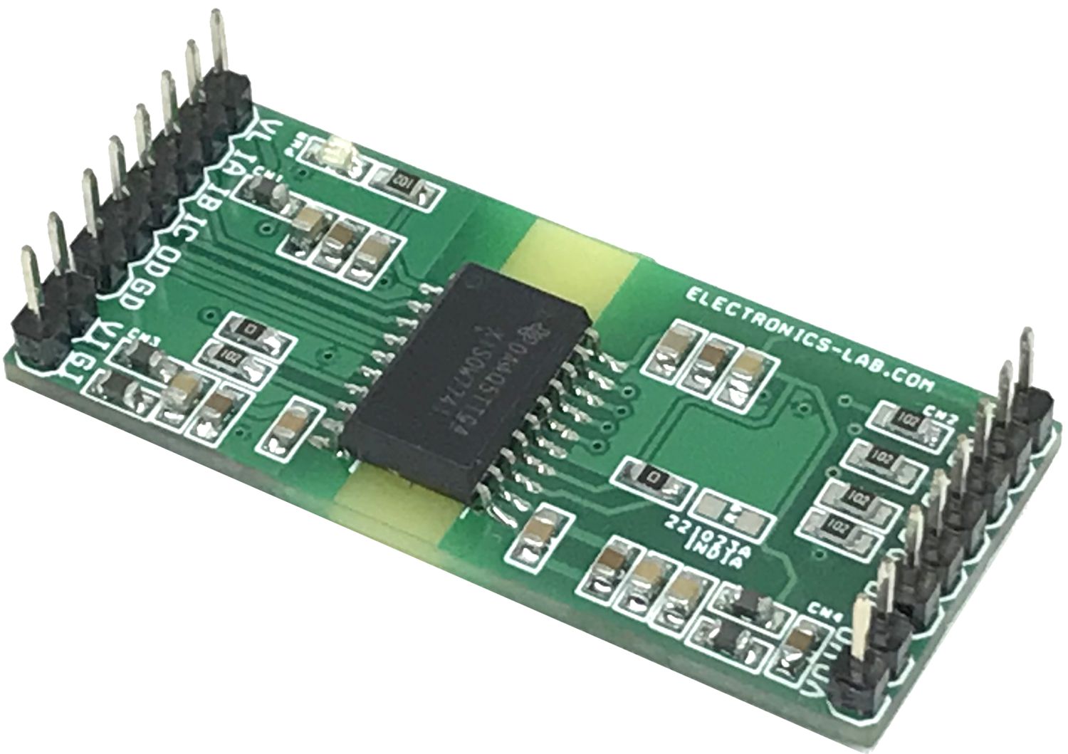
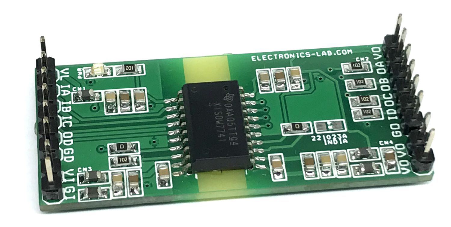
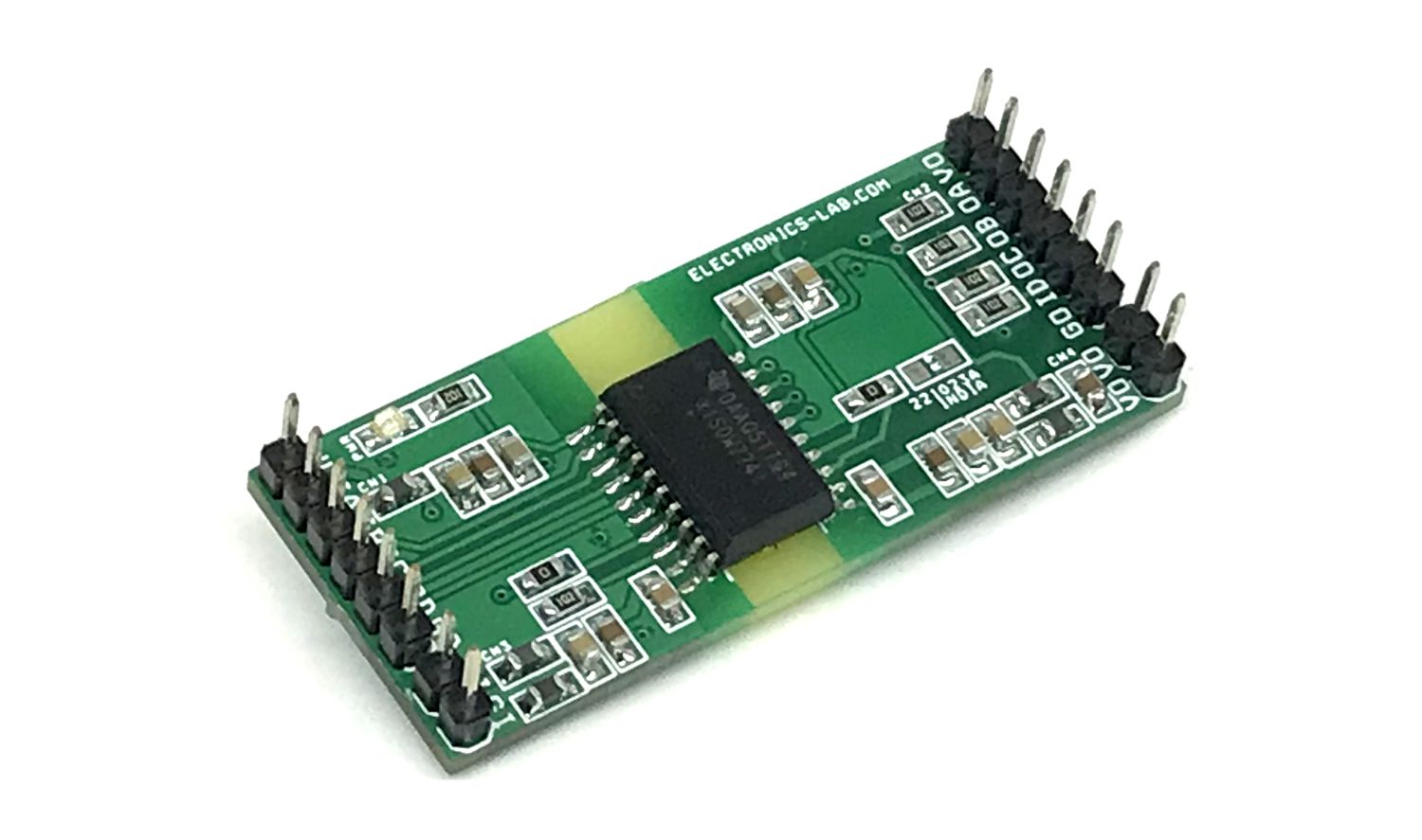
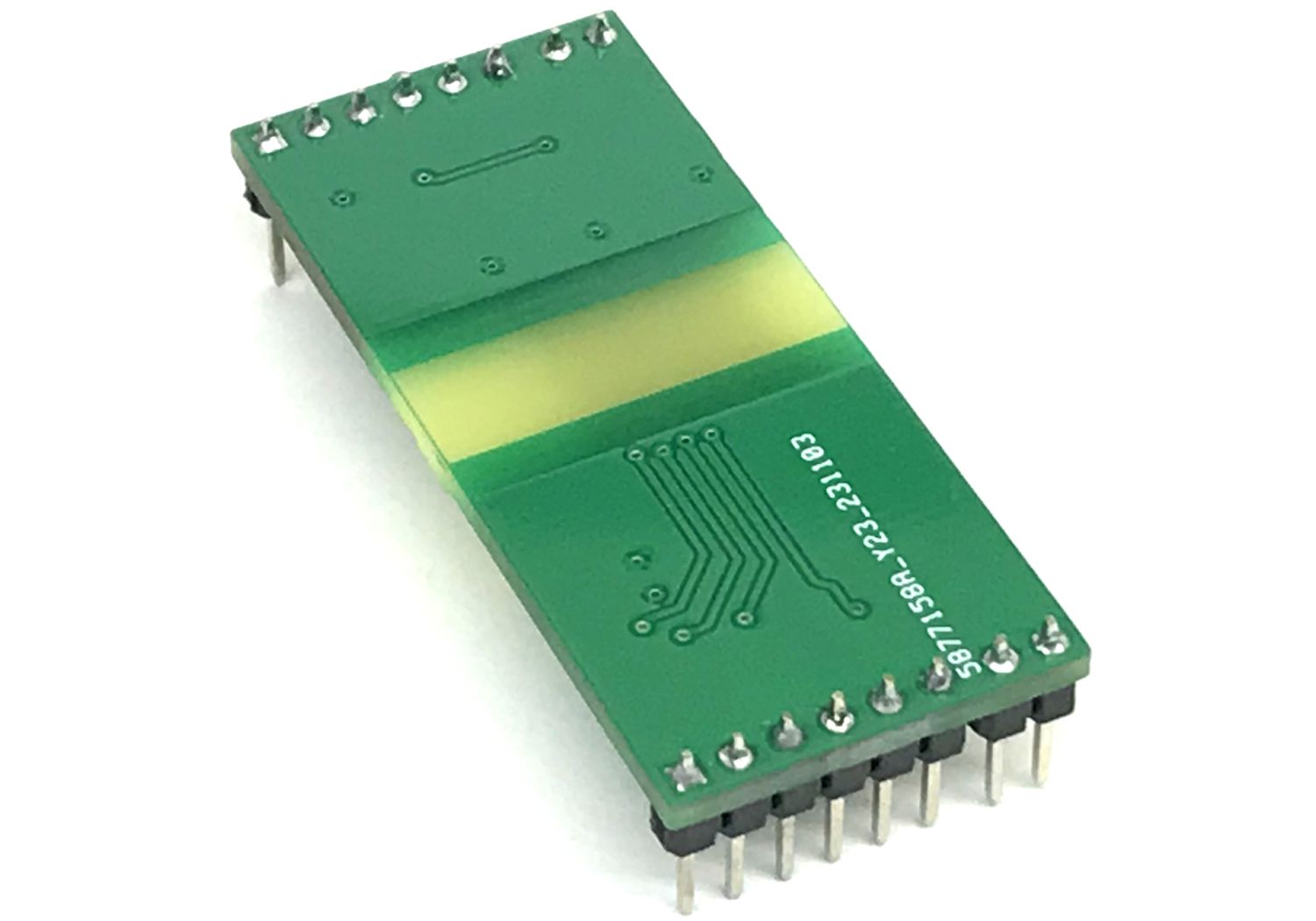
Photos
Video