

STEP/DIR SIGNAL TO CW/CWW SIGNAL CONVERTER FOR CNC & MOTION CONTROL SYSTEMS
- Rajkumar Sharma
- 20.993 Views
- medium
- Tested
- SKU: EL63188
- Quote Now
- 0 Likes

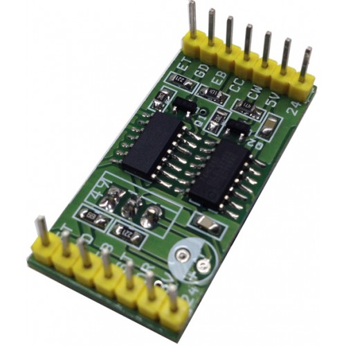
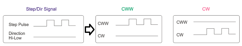
Simple Circuit converts Step/Dir. signal into to double drive CW/CWW Pulse, Mach3 and few Hobby CNC software’s provides Step/Direction pulse output to drive stepper motor drivers.
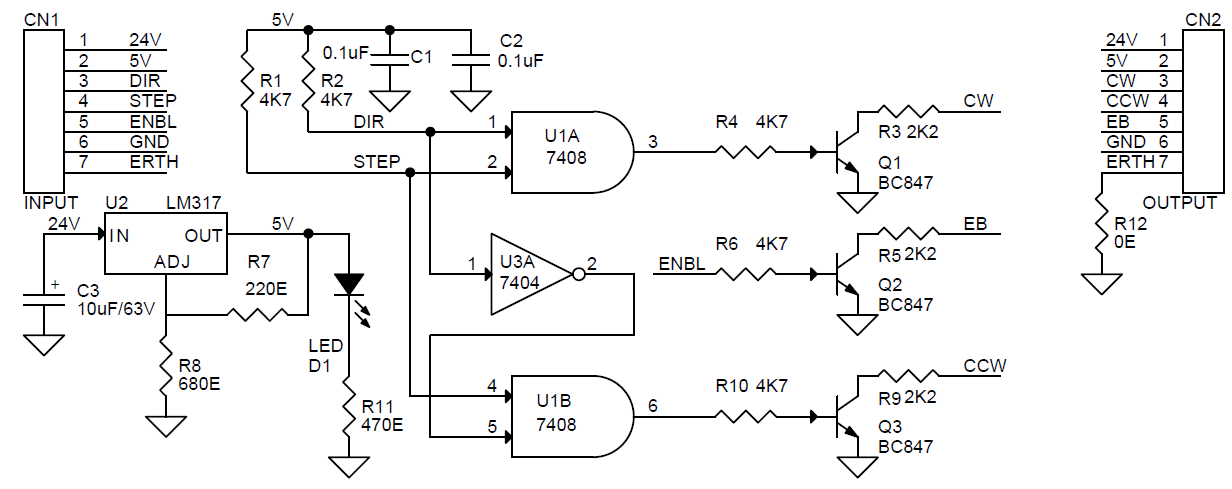
Various AC servo works with double CW/CCW pulse. This circuit is solution to interface such AC CW/CCW pulse based driver with Mach3 or other CNC software’s. Circuit designed around 7408 and 7404 IC, board support 5V or 24V supply. Open Collector output can be interface with 24V system by changing output resistors.
Features
- Supply 7V 24V DC
- On Board Power LED
- Inputs and Outputs Header Connector
- On Board ERTH (Earth) Signal provided for chassis ground to avoid any noise
Note : Output Transistor can drive Stepper Drive or Servo driver Opto-couplers directly , choose appropriate collector resistor value for 5V or 24V
- R3,R5,R9 470 Ohms for 5V DC Open Collector Output
- R3,R5,R9 2K2 Ohms for 24V DC Open Collector Output
Inputs:
- Step Pulse ( TTL 5V)
- Direction Pulse ( TTL 5V)
- Enable Signal ( TTL 5V )
Outputs:
- CW (5V Or 24V Open Collector)
- CWW ( 5V Or 24V Open Collector )
- Enable ( 5V Or 24V Open Collector )
Schematic
Parts List

Signal Diagram
Please follow and like us:
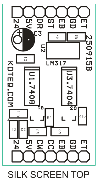
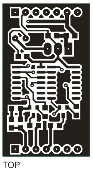
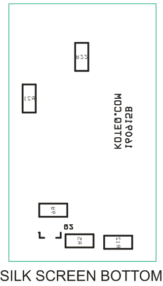
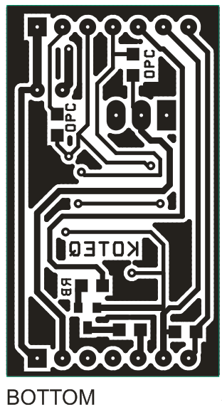
PCB


Thanks , great info and share , realy heplfull .
Thanks a lot !! but i have a question, What is the value of the resistors R21 and R22 in the bottom side ? I do not found on list.
I get it, in truth they are the resistors 1 and 2. thanks !
Hi,
Where we can buy this board?
I simply used a second arduino to convert dir/step signals to cw/ccw. Could not be simpler. Tried it with GRBL controlling a VEXTA 5-phase driver. Works!
Here’s the code:
int IN_GRBL_DIR = 3;
int IN_GRBL_STEP = 4;
int OUT_VEXTA_CW = 5;
int OUT_VEXTA_CCW = 6;
int ledPin = 13; // to test light led when cw is on
void setup() {
pinMode(IN_GRBL_DIR,INPUT);
pinMode(IN_GRBL_STEP,INPUT);
pinMode(OUT_VEXTA_CW,OUTPUT);
pinMode(OUT_VEXTA_CCW,OUTPUT);
pinMode(ledPin,OUTPUT);
}
void loop() {
int step;
int cw;
int ccw;
step = digitalRead(IN_GRBL_STEP);
if (digitalRead(IN_GRBL_DIR)==LOW) {
cw = step;
ccw = 0;
digitalWrite(ledPin,HIGH);
} else {
cw = 0;
ccw = step;
digitalWrite(ledPin,LOW);
}
digitalWrite(OUT_VEXTA_CW,cw);
digitalWrite(OUT_VEXTA_CCW,ccw);
}
Really ?!!
I can’t believe it was so simple
Thank you very very much ❤️
I want to use 3 drivers as a cnc grbl , so I guess then I need 12 pins 4 for any of them? Or another simple solution You will use ?
where can I buy this board?
check your email please.
Where can I buy this board?
Hola, necesito 3 circuitos hechos. Cual seria su precio?
Gracias.
Is this available anywhere to buy?
How many pieces do you need? We can manufacture this on order.
Hello. I am interested in buying 6 pieces if this is still available. I have a few omron servos and i wish to add them to a 3d printer( nema 24 mount) . They work in step/pulse or cw ccw mode
Please check your email. I sent you a quote.
I need it too
Hello, I am interested in purchasing 3 of the converters. Can you tell me where I can get them?
Thank you.
where can I buy this board?
Hi, are you still manufacturing this board? Where can I buy the board? Thanks
Please use the quote button to request a quote for this board. Thanks