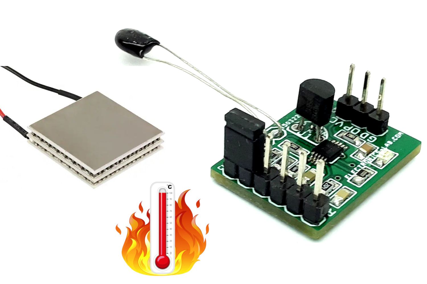
Thermistor Signal Amplifier for Thermoelectric Cooler using INA330
The INA330 breakout board is a great tool for TEC plate temperature measurements. The INA330 based precision amplifier is designed for thermoelectric cooler (TEC) control in optical networking applications.
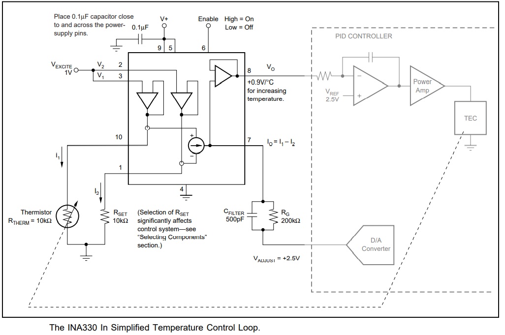
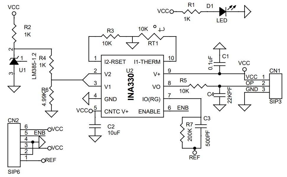
The INA330 breakout board is a great tool for TEC plate temperature measurements. The INA330 based precision amplifier is designed for thermoelectric cooler (TEC) control in optical networking applications. It is optimized for use in 10k thermistor-based temperature controllers. The INA330 provides thermistor excitation and generates an output voltage proportional to the difference in resistances applied to the inputs. The board uses only one precision resistor R3 plus the thermistor RT1, thus providing an alternative to the traditional bridge circuit. The circuit maintains excellent accuracy for temperature control applications. An excitation voltage is applied to the thermistor (RTHERM) RT1 and precision resistor (RSET) R3, generating current I1 and I2. The current conveyor circuit produces an output current, I0, equal to I1 – I2, which flows through the external gain-setting resistor. A buffered voltage output proportional to I0 is also provided.
The loop controls temperature to an adjustable set-point of 22.5°C to 27.5°C. The nominal 10kΩ at 25°C thermistor ranges from approximately 11.4kΩ to 8.7kΩ over this range. A 1V excitation voltage is applied to V1 and V2, producing a nominal 100µA current in the 10kΩ RSET resistor. The thermistor current is approximately 100µA at 25°C, but will vary above or below this value over the ±2.5°C set-point temperature range. The difference between these two currents flows in the gain-set resistor, RG. This produces a voltage output of approximately 0.9V/°C. The set-point temperature is adjusted with VADJ. Thus, the voltage at VO is the sum of (IO)(RG) + VADJ. VADJ can be manually adjusted or set with a Digital-to-Analog (D/A) converter. Optionally, the set-point temperature can be adjusted by choosing a different fixed-value resistor more closely approximates the value of RTHERM at the desired temperature.
Temperature Control Loop using INA330
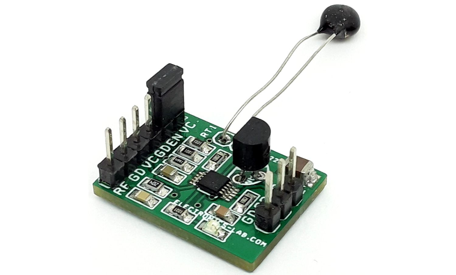
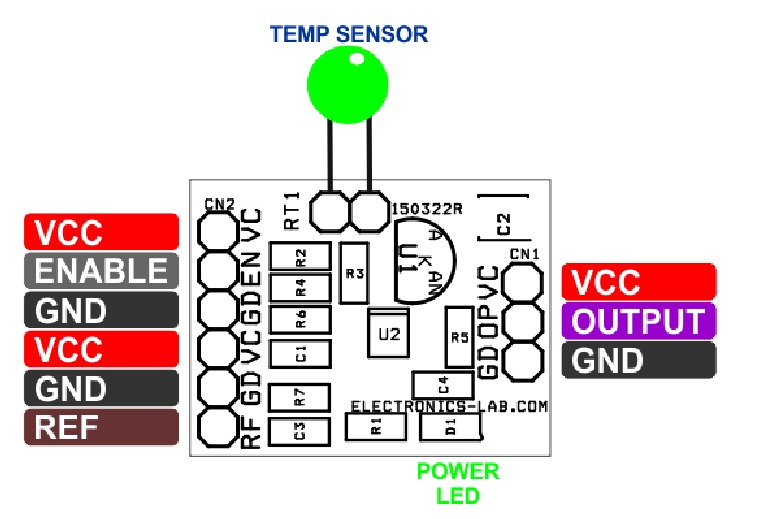
Connections and Important information
- CN1: Pin 1 = VCC 5V DC, Pin 2 = V Output, Pin 3 = GND
- CN2: Pin 1 = Reference Control Loop 0 to 5V, Pin 2 = GND, Pin 3 VCC 5V DC, Pin 4 = GND, Pin 5 = Enable-High/Disable-Low, Pin 6 = VCC 5V DC
- D1: Power LED
Features
- Supply 5V DC
- Reference Input 0 to 5V
- Output 0.9V/C Centigrade
- On Board Power LED
- On Board Precision Reference Generator Chip LM385
- PCB Dimensions 23.34 x 17.62 mm
Schematic
Parts List
| NO. | QNTY. | REF. | DESC. | MANUFACTURER | SUPPLIER | PART NO |
|---|---|---|---|---|---|---|
| 1 | 1 | CN1 | 3 PIN MALE HEADER PITCH 2.54MM | WURTH | DIGIKEY | 732-5316-ND |
| 2 | 1 | CN2 | 6 PIN MALE HEADER PITCH 2.54MM | WURTH | DIGIKEY | 732-5319-ND |
| 3 | 1 | C1 | 0.1uF/50V CERAMIC SMD SIZE 0805 | YAGEO/MURATA | DIGIKEY | |
| 4 | 1 | C2 | 10uF/16V CERAMIC SMD SIZE 1206 OR 1210 | YAGEO/MURATA | DIGIKEY | |
| 5 | 1 | C3 | 500PF/50V CERAMIC SMD SIZE 0805 | YAGEO/MURATA | DIGIKEY | |
| 6 | 1 | C4 | 22KPF/50V CERAMIC SMD SIZE 0805 | YAGEO/MURATA | DIGIKEY | |
| 7 | 1 | D1 | LED RED SMD SIZE 0805 | OSRAM | DIGIKEY | 475-1278-1-ND |
| 8 | 2 | R3,R5 | 10K 1% SMD SIZE 0805 | YAGEO/MURATA | DIGIKEY | |
| 9 | 3 | R1,R2,R4 | 1K 1% SMD SIZE 0805 | YAGEO/MURATA | DIGIKEY | |
| 10 | 1 | R6 | 4.99K 1% SMD SIZE 0805 | YAGEO/MURATA | DIGIKEY | |
| 11 | 1 | R7 | 200K 1% SMD SIZE 0805 | YAGEO/MURATA | DIGIKEY | |
| 12 | 1 | U1 | LM386-1.2V | TI | DIGIKEY | LM385BXZ-1.2/NOPB-ND |
| 13 | 1 | U2 | INA330 | TI | DIGIKEY | 296-13861-1-ND |
| 14 | 1 | RT1 | 10K 1% SMD SIZE 0805 | AMPHENOL | DIGIKEY | 235-1058-ND |
Connections
Gerber View
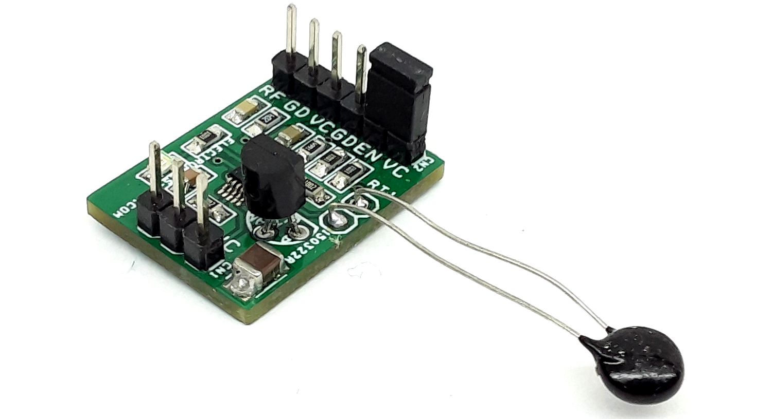
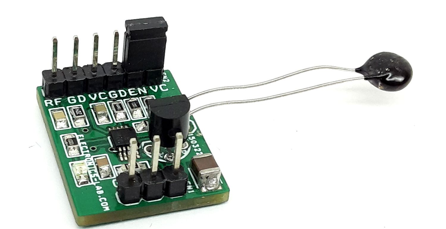
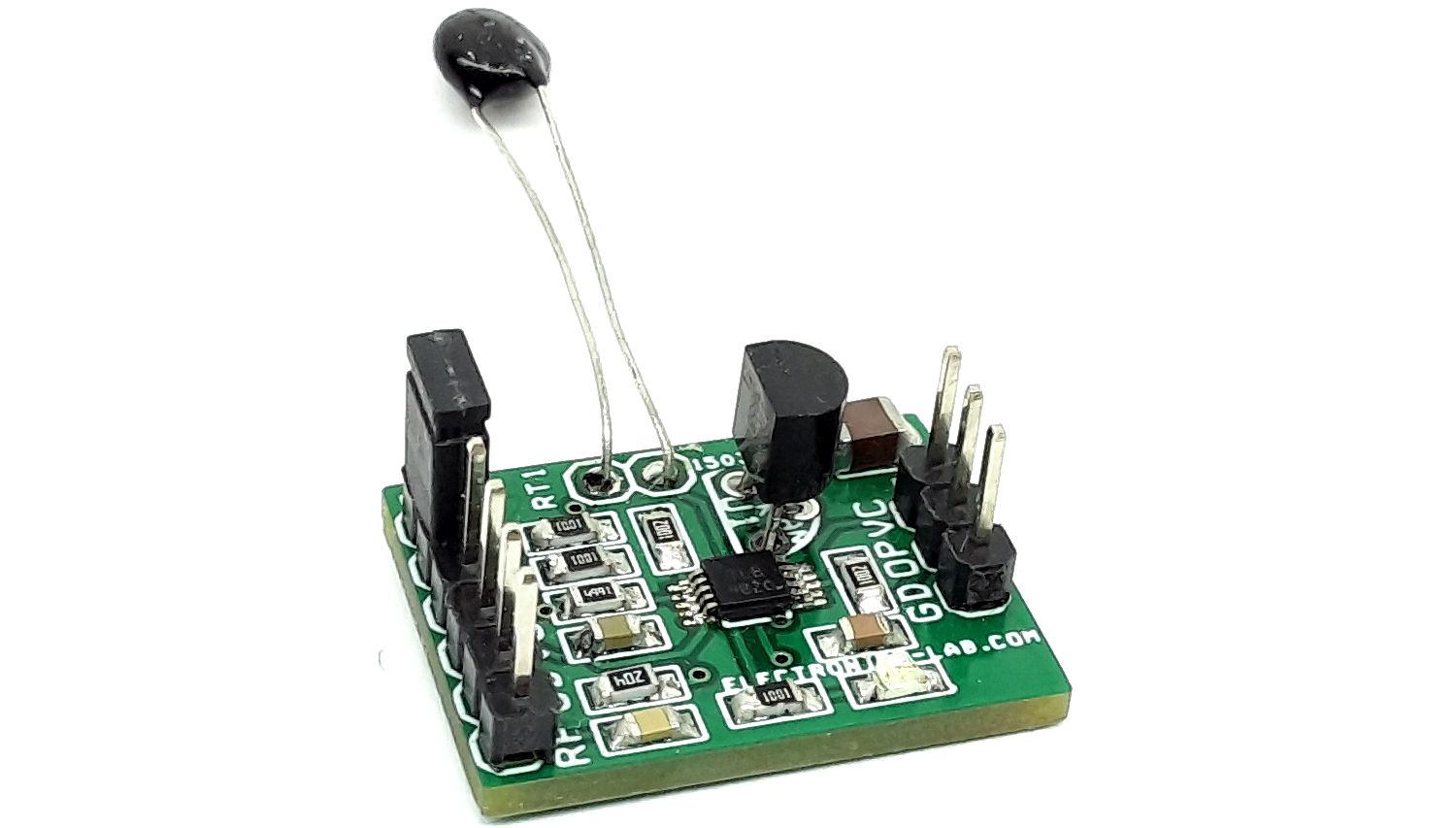
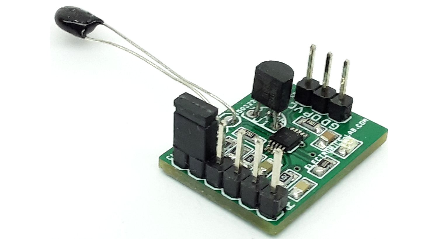
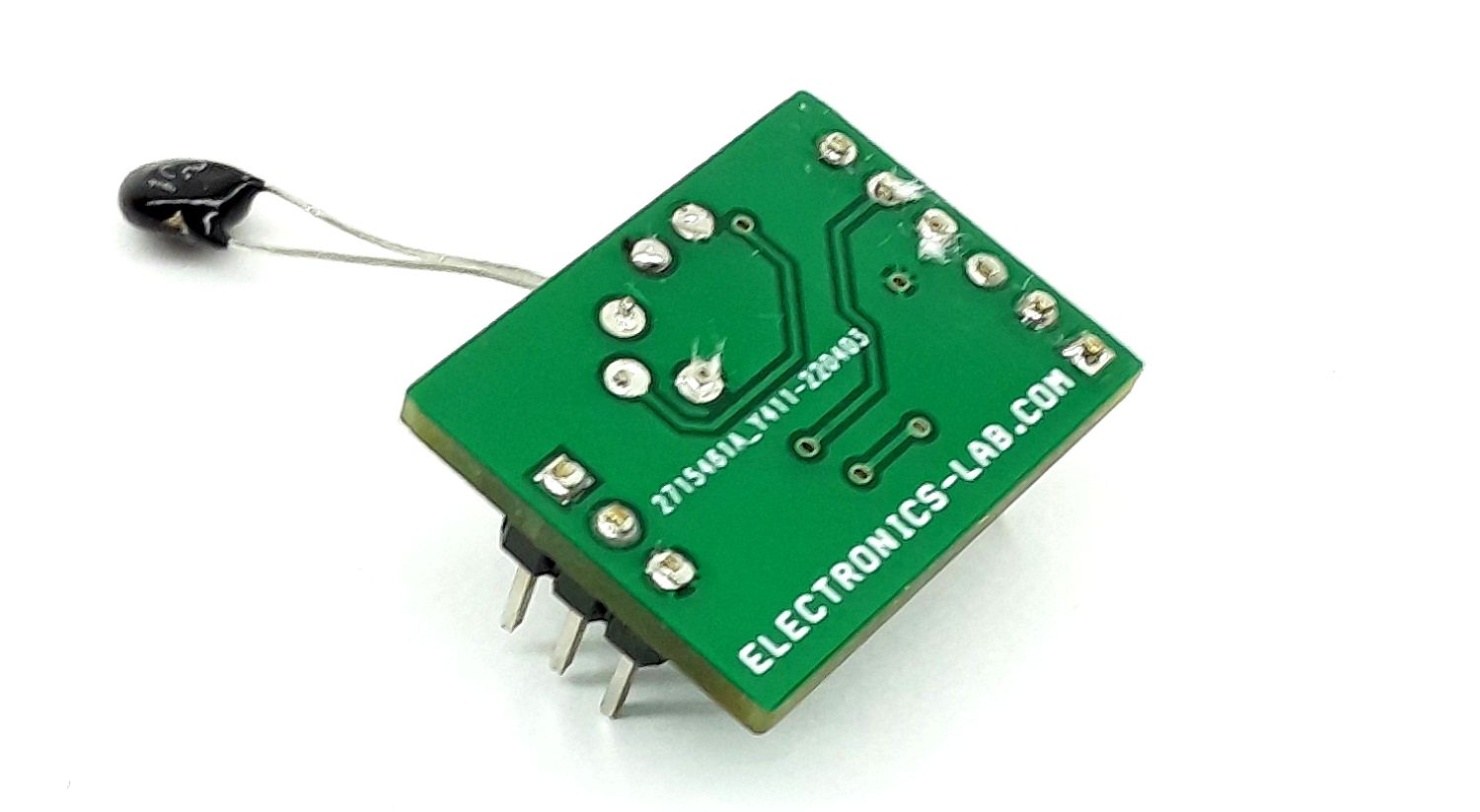
Photos