

2.5A Bipolar Stepper Motor Driver LV8772E
- Rajkumar Sharma
- 18.155 Views
- moderate
- Tested
- SKU: EL42835
- Quote Now
- 0 Likes

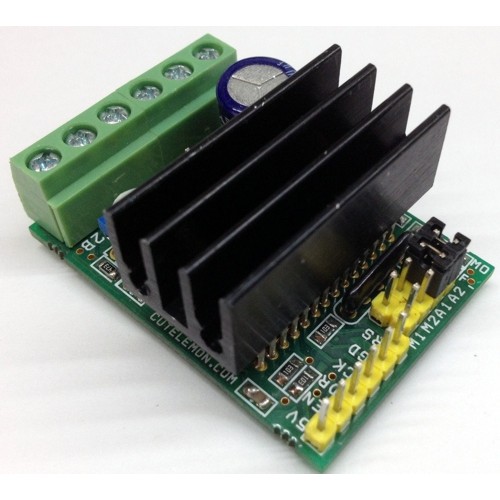
Tiny Board has been designed around LV8772 IC from On-Semi. This driver is capable of micro-step drive and supports 4W 1-2 phase excitation. It has Low on Resistance with motor current selectable in four steps. The board is equipped with unusual condition warning LED and input Pulse Monitor LED. It is most suitable for the drive of a stepping motor for OA, amusements, hobby CNC, 3D printers, automatic machines, linear guides, motion control systems, XY gantry, Camera focus and zoom controller, Mini camera Pan Tilt Head.
Specifications
- Power Supply input 9V to 30V (Max 32V)
- Output Current 2.5Amps
- Very low noise and smooth operations
- Very low noise in slow speed
- Low on resistance (Total of upper and lower: 0.55ohms)
- Micro-Step mode can be set to Full-Step, 1/2 Step,1/4,1/16 Steps
- Motor Current selectable in four steps
- Output short circuit protection circuit incorporated (IC)
- Built in thermal shutdown circuit
- No Control power supply required
- Input Signals 1. Step (Clock) 2. Direction 3. Enable 4. Reset
- This Drive default set to enable and reset
- Current Setting via onboard Preset (Potentiometer)
- Attenuation ATT1 and ATT2 by Jumpers
- Two Jumpers for Micro-Step settings
- On-Board Fault Warning LED
- On-Board Pulse Input indication LED
Applications
- Slot Machine
- Vending Machine
- Cash Machine
- PPC (Plain Paper Copier)
- LBP (Laser Beam Printer)
- Scanner
- CNC
- 3D Printers
- Textile
- Camera Pan Tilt Head
- Camera Focus and Zoom Controller
Chip Enable Functions (Default this pin set to high for normal operation)
- ST Pin High Operation Mode, Low Disable the drive
- This IC is switched between standby and operating mode by setting the ST pin, In standby mode, the IC is set to power-save mode and all logic is reset. In addition, the internal regulator circuit and charge pump circuit do not operate in standby mode.
Position detection monitoring function (LED MO, D2)
- When the excitation position is in the initial position, the Monitor output LED MO D2 placed in the ON State
Setting constant-current control reference current (PR1 Potentiometer)
- Potentiometer PR1 is to set the Current
RESET Function (Default this pin set to normal operation using pull down resistor R10)
- Reset Pin Low = Normal Operation, Reset Pin High = Reset State
- When The RST pin is set to High, the excitation position of the output is forcibly set to the initial state, and the Moni -D2 LED is in ON state, When RST is set to low , the excitation position is advanced by the next STEP input
Output Short Circuit
Output Short-Circuit protection type of IC is latch type to turn off when the output current exceeds the detection current and the state is maintained. The output short-circuit protection circuit is activated in and event of short-circuit in the output pin. When the short-circuit state continues for a period of time set by the internal timer (approximately 4uS), the output in which short-circuit was first detected are switched to the standby mode, And if the short-circuit state is still detected, all the outputs of the channel are switched to the standby mode, and the state is held, this state is released by setting ST to low.
EMO Unusual condition warning output pin (Fault LED D1)
This board is provided with EMO (Fault LED) which notifies the CPU of an unusual condition if the protection circuit operates by detecting an unusual condition of the IC, When an unusual condition is detected , the Fault LED D1 is placed in the ON (EMO=Low)
Chopping Frequency
- F-Chop 10uA/180PF/).5VX2=55Khz
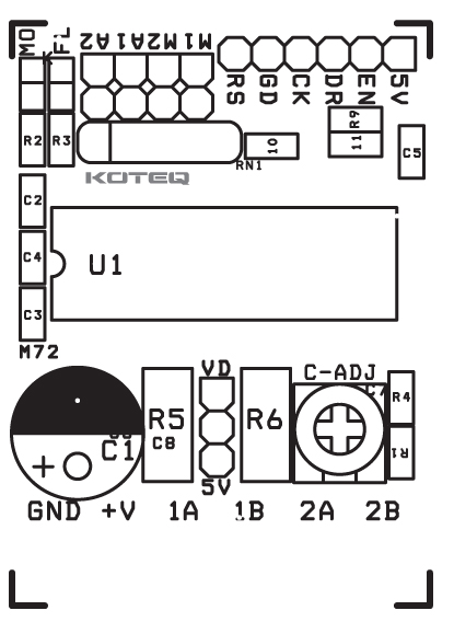
Connections
CN1: Power Supply In
CN2: Bipolar Stepper Motor Connections
CN6: Control Signal Inputs ( All inputs are TTL Level)
- Pin1 5V : DC Aux ( Output)
- Pin 2 ENB : Enable ( Default set to Enable , Required low input (Pull Down) to disable)
- Pin3 CK : Clock input to excite the motor ( Pulse Inputs)
- Pin 4 : GND Ground Signal
- Pin5 : RS : Reset input
PR1: Onboard Preset (Potentiometer) to set the Current
D1 : Fault LED
D2 : Pulse Monitor LED
CN5 : Aux. Power Supply Output , Supply 24V, 5V Regulated, Ground
M1, M2 : Jumpers to set the Micro-stepping
A1,A2: To Set the Motor Holding Current (A1=ATT1, A2=ATT2)
| MICRO-STEP SETTINGS | |||
| SR | M1 | M2 | Micro-Step RESOLUTION |
| 1 | LOW | LOW | FULL STEP |
| 2 | HIGH | LOW | HALF STEP |
| 3 | LOW | HIGH | QUARTER STEP |
| 4 | HIGH | HIGH | 1/16 STEP |
| JUMPER CLOSED=LOW I JUMPER OPEN= HIGH | |||
Current Setting Reference Voltage Attenuation Ratio (A1 & A2 Closed= Low, Open=High)
- ATT1-A1 Low I ATT2-A2 Low = 100%
- ATT1-A1 High I ATT2-A2 Low = 80%
- ATT1-A1 Low I ATT2-A2 High = 50%
- ATT1-A1 High I ATT2-A2 High = 20%
The formula used to calculate the output current when using the function for attenuating the VREF input voltage is giving bellow
- I out+(VREF/%)X(Attenuation Ratio)/RF resistance
Example: At VREF of 1.0V, a reference voltage setting of 100% (ATT1-A1=Low ATT2-A2=Low) and an RF resistance of 0.5 Ohms, the output current is set as shown bellow,
- I-Out=1.0VX5X100%/0.22Ohms=0.91A
If, in this state (ATT1-A1=High, ATT2-A2=High), I-Out will be as follows:
- I-Out =0.91AX50%=455Ma
In this way, the output current is attenuated when the motor holding current is supplied so that power can be conserved.
Schematic

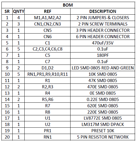
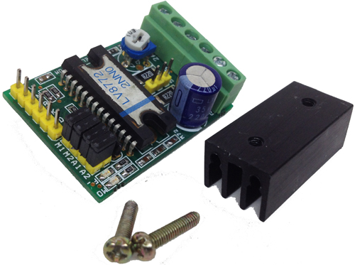
Parts
Photos
Video
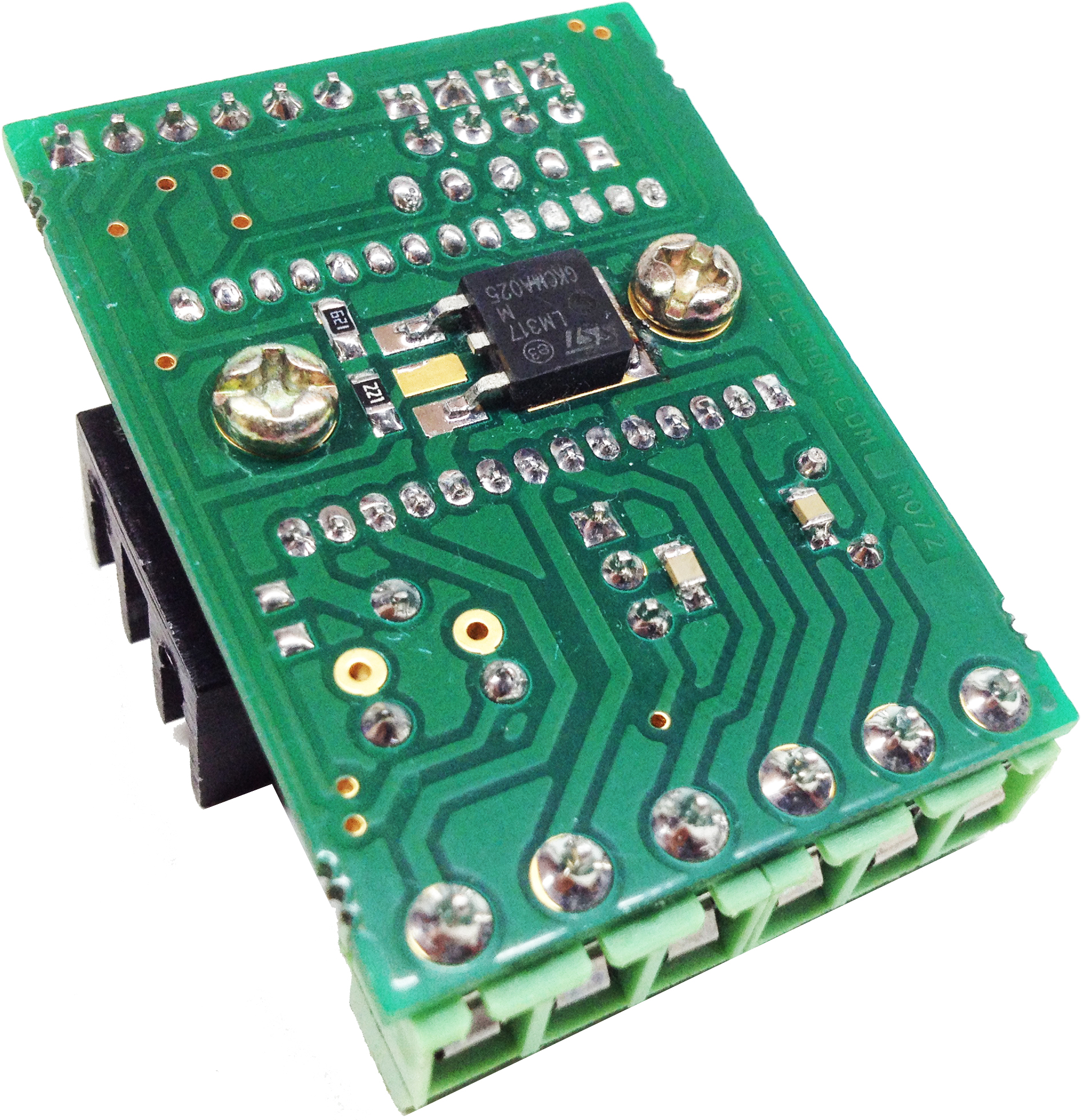
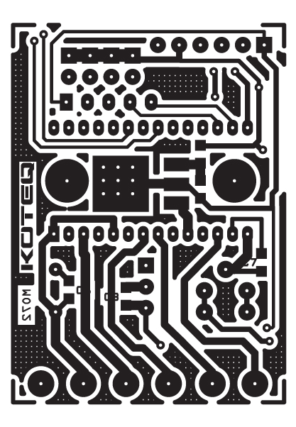
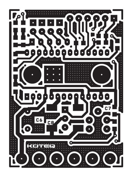
PCB


Hello … congratulations for your project, it is very practical and simple … thanks for sharing your knowledge.
I require this project already assembled.
Can you sell them to me?
I also need the driver.
If yes, please send the quote to ghaester @ gmail.com
Thank you
Gustavo Aristizabal