XBMC USB Controller
- Dilshan R Jayakody
- jayakody2000lk@gmail.com
- 28.115 Views
- medium
- Non tested
- 0 Likes

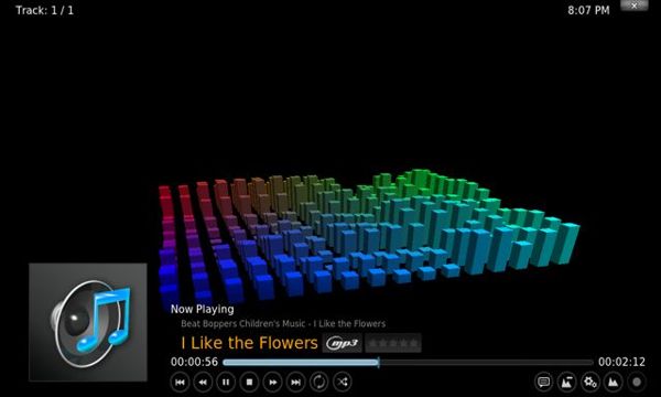
Fig.1 – XBMC Audio Player
For Media Center PCs
 XBMC is a cross platform Media Center Application with 10-foot UI. In this project we develop USB port base controller for XBMC application. Main functionality of this controller unit is to provide remote control interface, LCD base player information panel and rotary encoder base controller for XBMC. With this given hardware design and software programs, user may be able to control XBMC without using standard input devices such as keyboard and mouse.
This device is design to work with XBMC Version 10.1 (codename Dharma) or newer versions. Older version of XBMC may not work this system because of the differences in its Web Control Interface. This system is design to work with XBMC – JSON RPC interface.
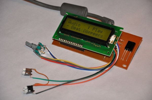
Fig.2- XBMC USB Controller
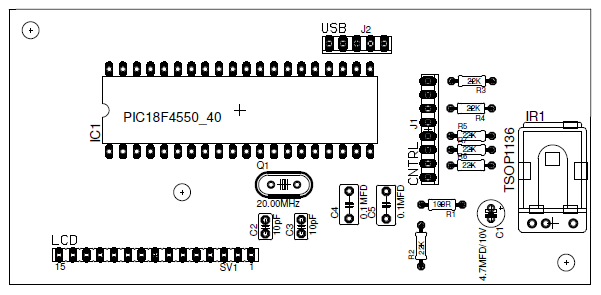
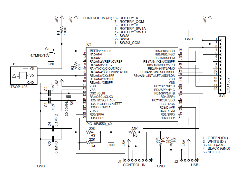
Microchip’s PIC18F4550 is a main hardware controller of this system. This microcontroller is used for USB interfacing, as LCD driver, IR base remote control data decoder and as a driver of the other input devices (such as rotary encoder and push switches). XBMC Controller’s USB interface is design to work as a USB HID class device.
This system is design to work with Microsoft Windows Operating Systems and we test this system in Windows XP Professional editions and some few Windows XP Embedded editions also. Supplied firmware of this system is design to work with Sony SIRC 20bit infrared protocol and supplied ini file is configured for Sony RMT-V408 remote controller.
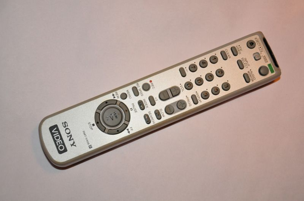
Fig.3- Sony RMT-V408 Remote Controller
Software Content
This system consists with two main software modules:
1. PIC18F4550 base software (firmware): This software module is developed using MikroC version 4.60.
2. Windows XBMC control application: Developed using Delphi 7 and work as a “virtual” Windows Service Application.
Before work with this system end user need to configure controller application for his/her remote control and for his/her software setup. This configuration file is located at \Controller\release folder with filename “mcci.ini“.
This ini file contains 3 main sections such as “xbmc“, “device” and “keymap“.
“xbmc” section contain 3 parameters:
Address: IP address of the system where XBMC is installed. (In most of the configurations this parameter value set to defaults as 127.0.0.1)
Port: Port number assigned for XBMC web interface. (This value is need to verify with your XBMC network settings)
Location: full path and filename of the XBMC executable file.
“device” section contain 2 parameters related with the USB controller. If your using default firmware, these values must be VID = 33824 and PID = 1.
If you alter firmware with different vendor ID and product IDs, make sure to change these values also.
“keymap” section is used to assign functionalities to the remote control buttons. Key and the value formats for this section are described in below.
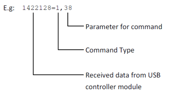
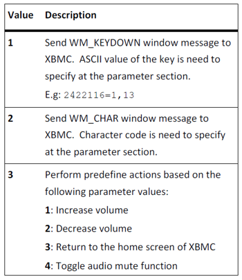
Command Type: Specify the type of the command as integer value. Valid command types are:
“keymap” section is used to assign functionalities to the remote control buttons. Key and the value formats for this section are described in below.
USB Controller – hardware connections
This given PCB design have 2 external connectors. J1 connector is used to connect rotary encoder and two push switches to the system. Connection diagrams of the J1 is illustrated in Fig. 4. J2 connector is used to connect USB cable to the system. Connections to the J2 is listed in below table:
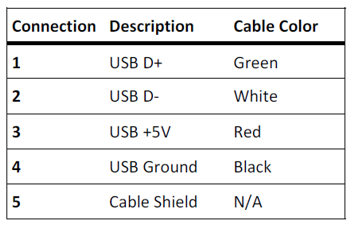
For J2 use standard 3feet 28/24AWG USB cable with USB male A connector.
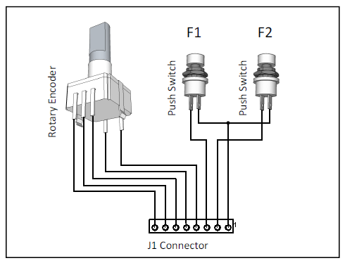
Fig.4- Connections to Connector J1
Installation and Initial Setup
Before start the initial setup we assume that target PC may have following minimum system requirements:
-
Windows XP or newer version of Windows operating system
-
XBMC 10.1 or newer version
-
USB 2.0 port
-
Suitable SIRC protocol base remote controller unit
If the target system meets the above specified requirement, continue the system setup process as follows:
-
Start XBMC and Click “System” and open “Network” tab.
-
Under the “Services” change the following options: Allow control of XBMC via HTTP : ON Port : 80 Username : Password : (Clear both username and password fields)
-
Press “Esc” key.
-
Close XBMC.
-
Extract supplied software package and make sure that mcci.ini file is properly configured.
-
Connect XBMC USB controller to the PC. If device is working properly, Windows automatically detect the device and configure it to the target system.
-
Start mcci.exe application. If everything is properly configured, XBMC starts automatically.
-
Check the all XBMC functionalities with remote controller and controls on the XBMC USB controller.
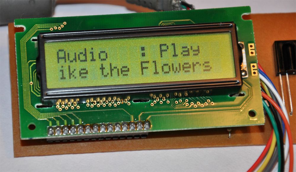
Fig.5- XBMC player information
Technical Specifications of the Device
Please note that all these technical specifications are valid only with the bundled firmware file (Version 1.0.0.31).
- USB Version : 2.0
- Device Class : 0x0
- Vendor ID : 0x8420
- Product ID : 0x1
- Manufacturer : Dilshan R Jayakody
- Product : Media Center Control Interface
- Product Version : 0.1
- Power Mode : Self powered 100mA Max
- USB interfaces : 0x3 – HID class
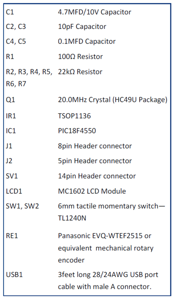
Components List
References
- PIC18F2455/2550/4455/4550 Datasheet: 39632e.pdf
- IR Receiver Modules for Remote Control TSOP11xx: tsop11xx.pdf
- JSON RPC – XBMC: http://wiki.xbmc.org/index.php?title=JSON_RPC
- JSON-RPC 2.0 Specification: http://groups.google.com/group/json-rpc/web/json-rpc- 2-0?pli=1
Schematic

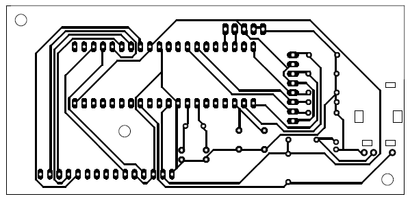
PCB