
MCU Controlled Spot Welder
- Hercules Trapierakis
- herctrap@yahoo.gr
- 41.424 Views
- advanced
- Non tested
- 0 Likes


This project is a controller for a dual pulse spot welder that has some nice features that are controlled using a LCD interface.
Description
I always wanted a spot welder, so I decided to built one. I wanted to build a capacitance discharge one but I couldnt afford for the capacitors at this time. So this is a controller for a dual pulse spot welder with some few extras:
- It has a zero cross detector. You could power the transformer at zero cross or dim the transformer if you like
- The transformer is triac controlled
- It has an hd44780 interface
- An spi interface for single thermocouple
- Peak detector of a current transformer
- Isolated foot switch
- Voltage monitor with opmaps
- An attempt to sense when the user tries to weld
- Single rotary switch for operation and single rotary encoder for setting up
I have used an Atmega328P and I will probably write the code in arduino IDE.
You could probably use the pcb for other applications, like:
- Ac dimmer
- Simple thermostat, or
- PID thermostat with dimming output
Further update on the project after the delivery on the pcbs.
Schematics
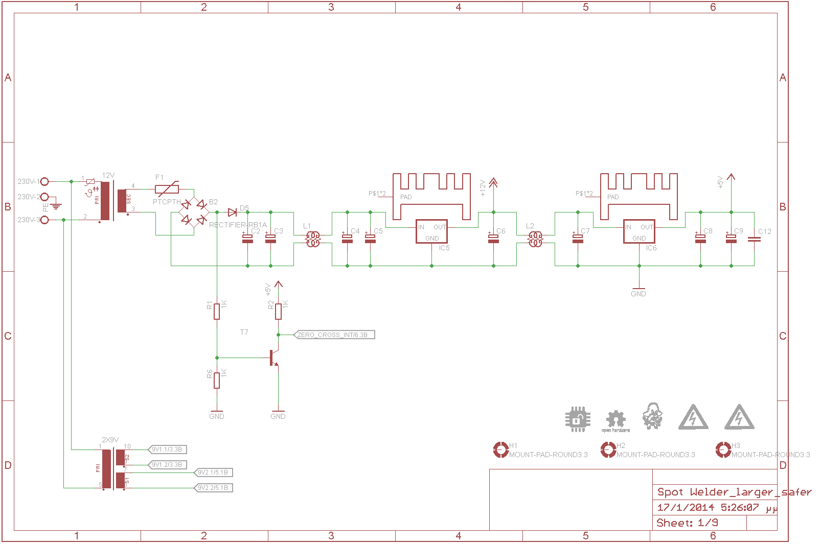
The main power supply for the controller. The main transformer is 1x12VAC 1Amp (TR-15)
The PTC fuse is 0.9A with a 2W10 bridge rectifier and a 1n4007 diode, smoothing capacitors, common mode choke to remove any spikes and unwanted noise, some more capacitors, linear voltage regulator 7812 with heatsink, more caps, more chokes, more caps again, 7805 and 5v rail.
The T7 is a 2n3904 npn transistor that senses both of the AC zero crosses for the dimming circuit.
The other transformer is a 2x9Vac 0.1Amp for the secondary isolated circuits.
Power OK
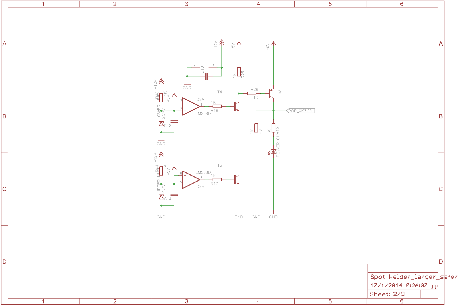
I had some space I thought to make a voltage supervisor of the 5V rail.
The two opAmps works as comparators for the 5V rail. The first IC3A checks if the voltage on the non inverting input is lower than the zener voltage (5.3V), if so the output of the opAmp is set High (12V) and T4 is turning on.
The IC3B checks if the voltage is higher than the zener voltage ( 4.7V), if so the output of the opAmp is set High (12V) and T5 is turning on.
Now if both transistors are ON then Q1 turning on and powering the led and setting the PWR_OK signal high.
Foot Switch
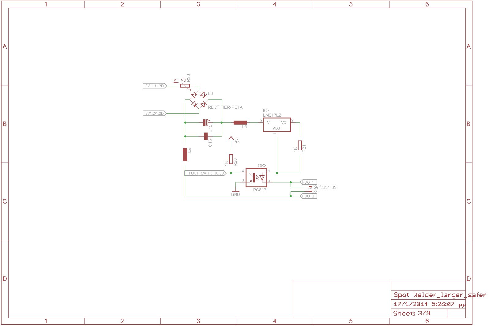
This is an opto-Isolated switch input to the uC. 9V comes in from the transformer, B3 is also an 2W10 bridge rectifier with some smoothing capacitors and two in series inductors powering a LM317 (TO-92) working as a constant current driver for the opotcoupler led. If you close the switch the led turns on and the signal FOOT SWITCH goes low.
Current Measure
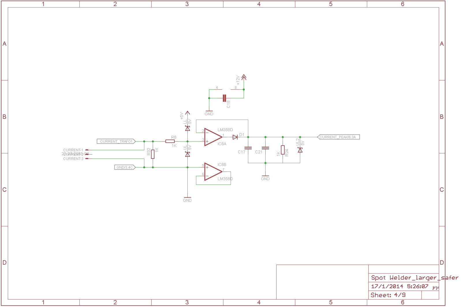
This circuit connects to a current transformer and measures the peak current of the weld. The current waveform is feeding to the non inverting input of IC8A, the two zener diodes protect the input of the opAmp from voltages lower than 0V and higher than 5V. D1 is only allowing the opamp to charge the capacitors at the peak voltage of the current transformer and zener diode protects the input of the uC.
Electrodes Touch
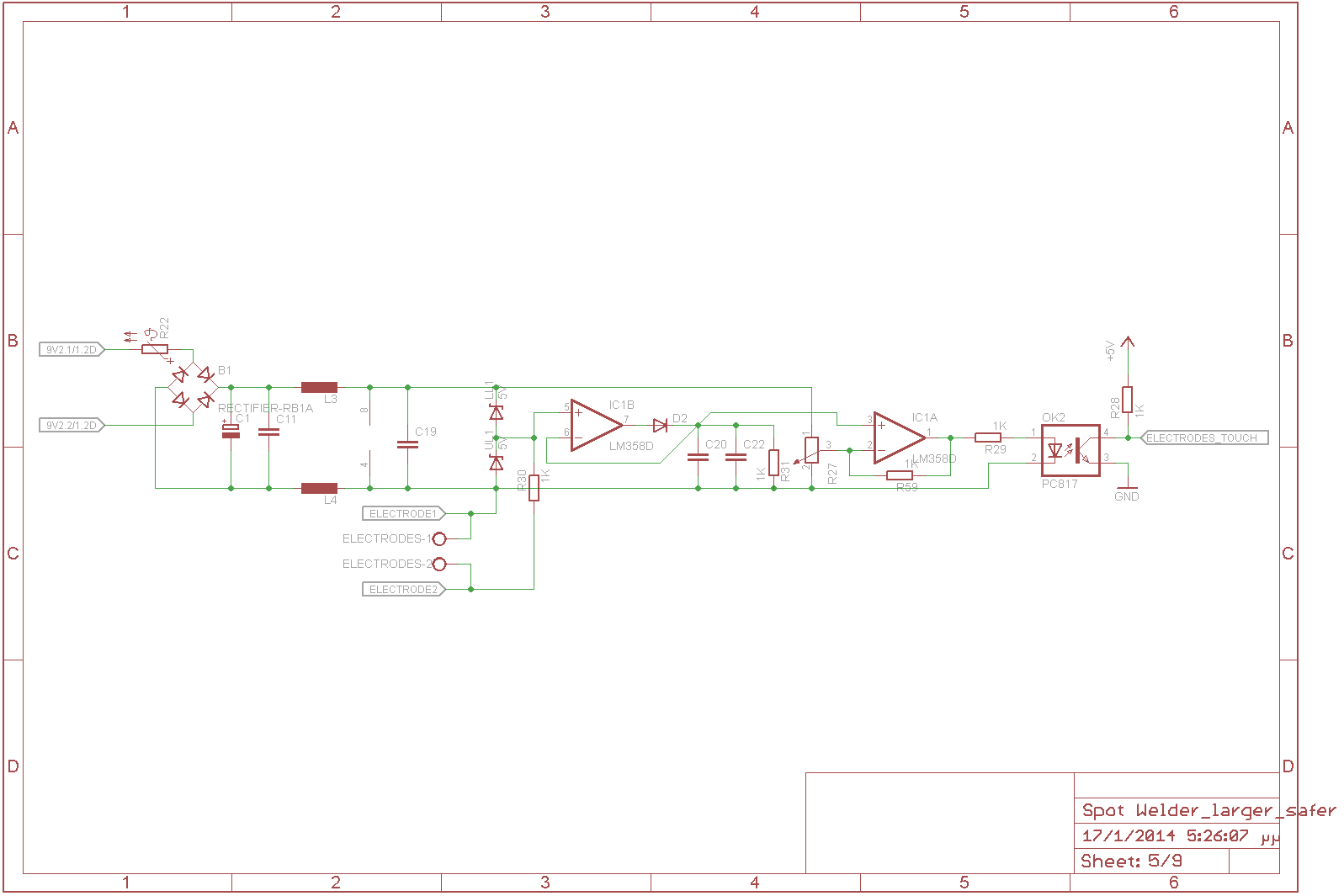
This circuit is an to attempt to automate the spot welder. The idea is to sense when the user places the electrodes on the battery and after a short delay and a buzz to power the transformer. But I think is going to fail. I am going to try to power the weld transformer a little bit before the zero cross.
If the current is zero then the user is not trying to weld or if the voltage across the the two leads is higher that a limit then the user is not trying to weld ( the electrodes are not shorted ).
The same isolated power supply as before and the same peak detector but this time the output of the peak detector is feeding two a second opAmp working a comparator. If the output of the peak detector on the non inverting input of the opAmp is lower than the set voltage on the inverting input from the 10-turn pot the output of the opamp is high, the led turns on and the signal ELECTRODES_TOUCH goes low.
uC
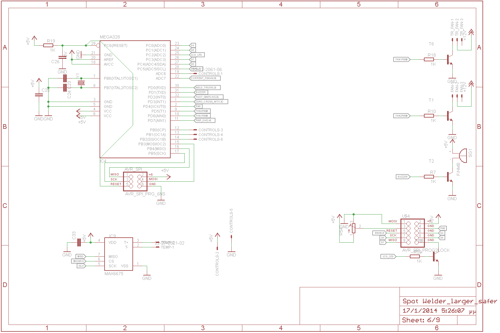
The uC is an AtMega328 in tqfp32 package running at 16Mhz and the code will be written in Arduino IDE There is an spi thermocouple interface MAX6675 for the weld transformer, two PWM controlled fan headers, a buzzer and U$4 is for the LCD with Hitachi HD44780 controller.
Switch
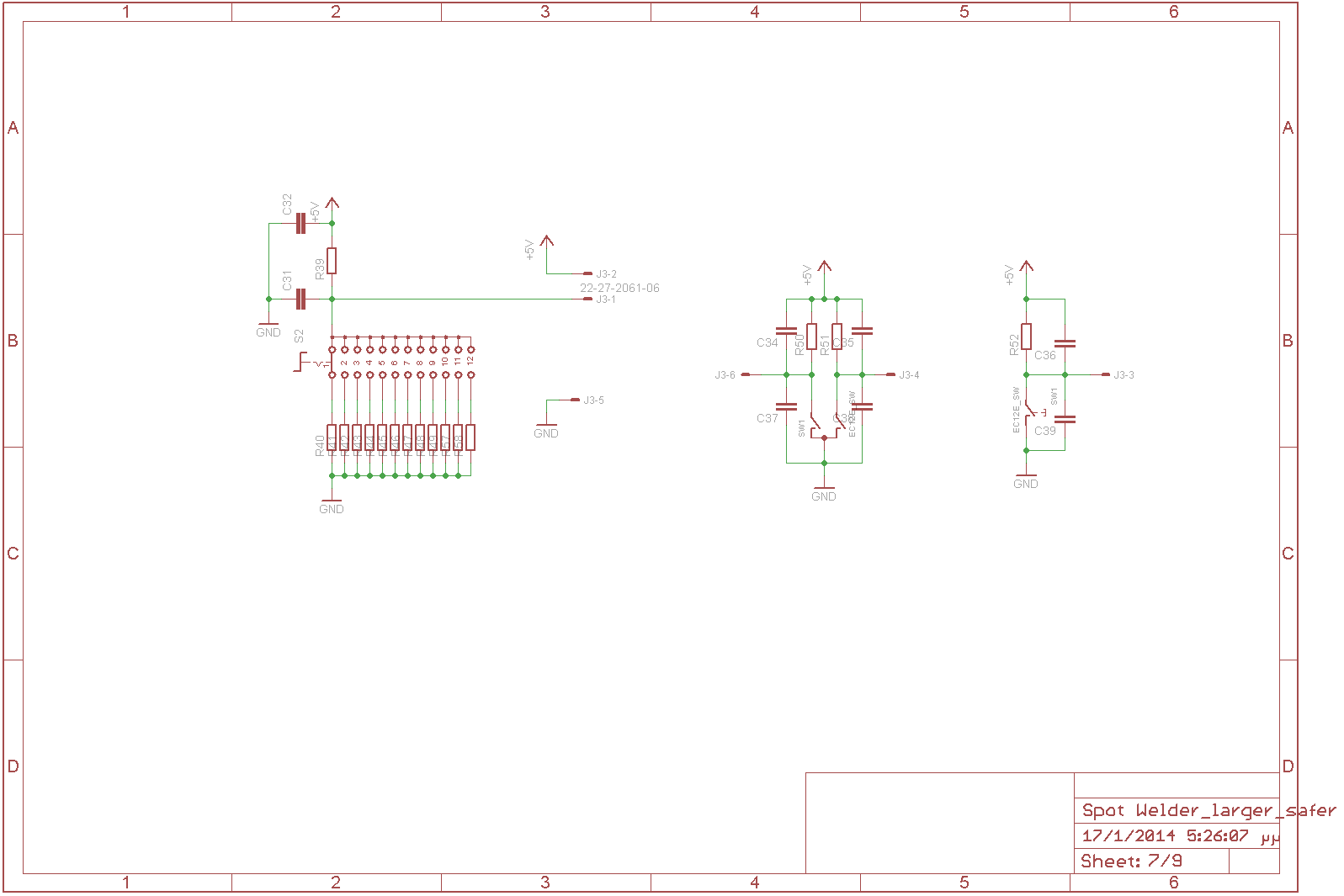
The interface with the user is pretty simple. There is 12 position rotary switch for the 12 preset modes of operation and a rotary encoder with a push button for navigating in the menu and setting the preset modes of operation.
Weld transformer controll
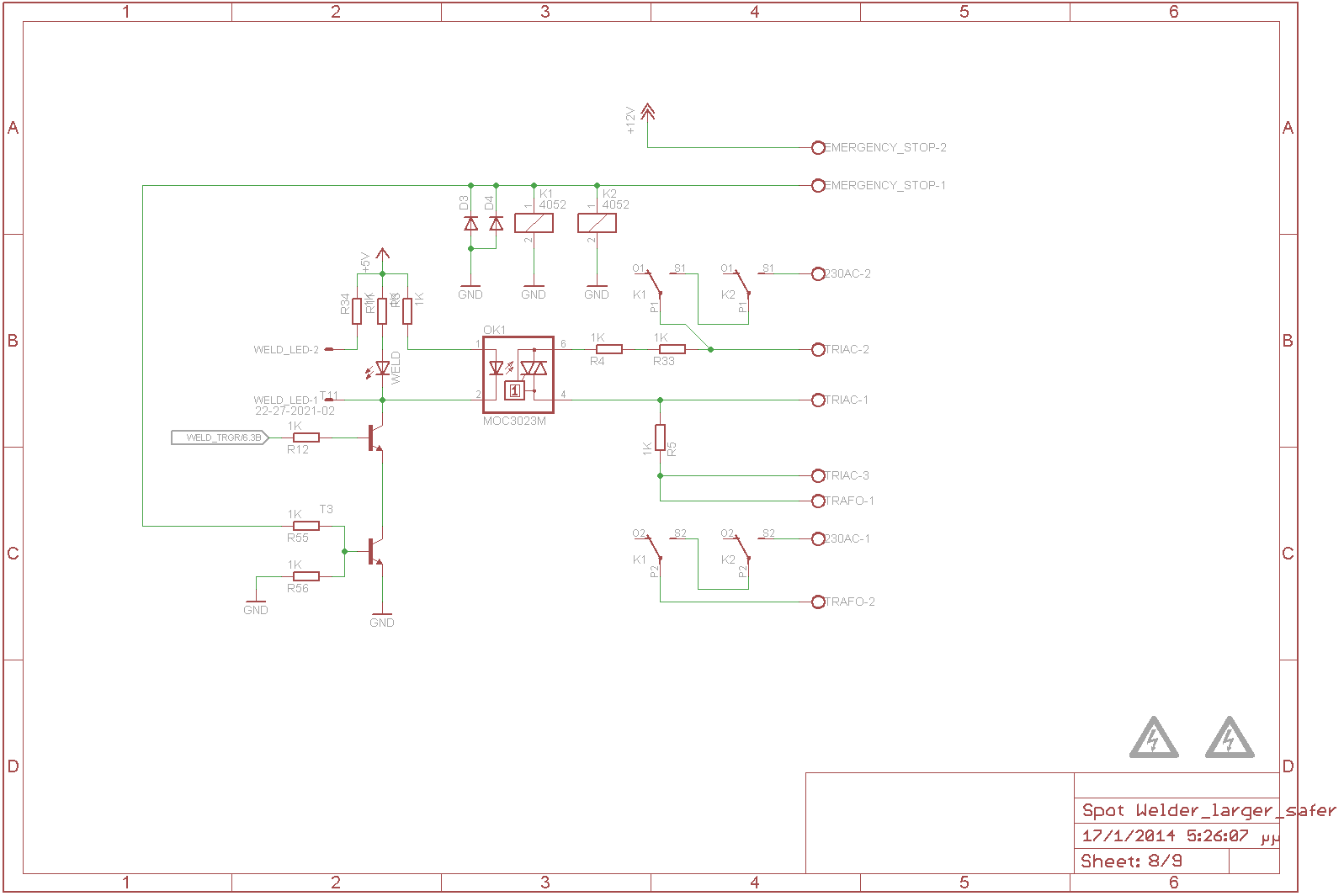
K1 and K2 are two 12Vdc coil relays with dual pole dual throw contacts. Live and natural line are passing through the contacts of both of the relays and the relays coils are triggered by the normaly closed emergency stop button, as well as the led on the opto-triac needs the 12V from the emergency stop button. Also there is a led that switch on when the opto-triac switch on and a pin header for a led closer to the transformer.
Snubbers
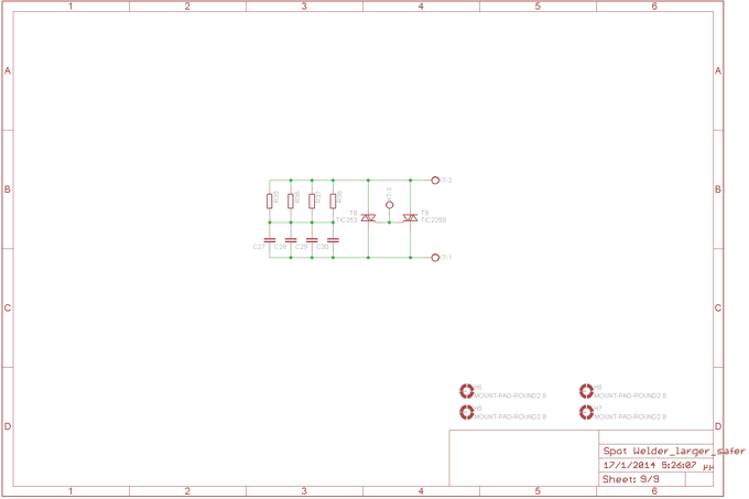
Just a separate pcb for the RC snubber circuit with multiple pads for various packages of resistors, capacitors and triacs.
Photos
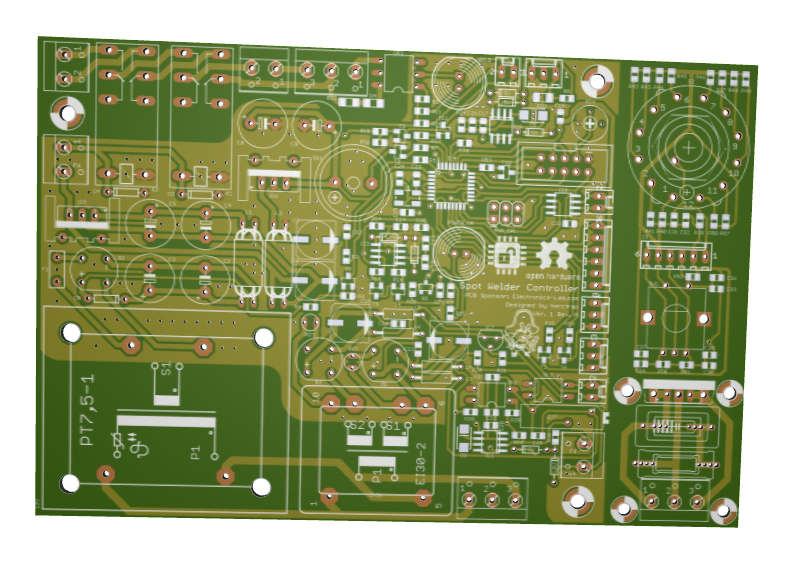
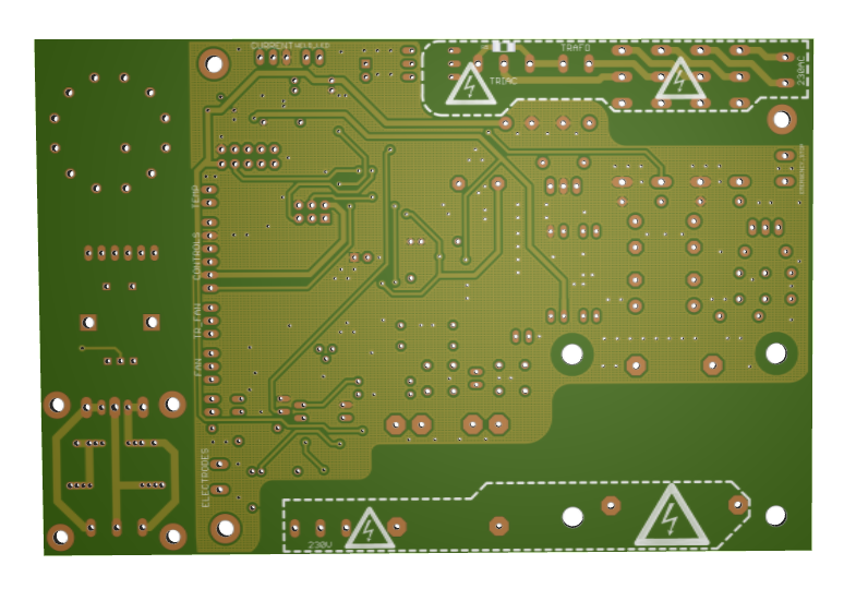
3D PCB renderings
Please follow and like us:
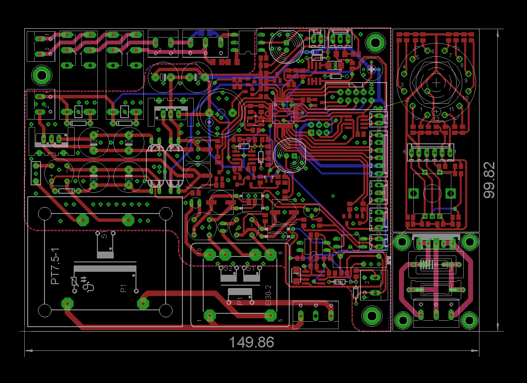
PCB


")
Please provide a Bill of Material(s) and component size and values for the MCU Spot Welder schematics.
Thank you
Please email the author found below the project’s title.
Let us know whether programs are written. Can we have a copy for our tryout.
You may try to contact the author about this project.
How to get the code
I think the spot welder can be automated, as in to detect when the electrodes are shorted or in other words when the electrodes are placed on the nickel strips by sensing the voltage drop at the primary terminals.
hello
please can you send c code files
Please contact the author for asking about source code and project status. Thanks
HOW ABOUT THE CODE OF MCU CONTROLLED SPOT WELDER, PLEASE TELL ME ,SIR THANKS !
Do not waste your time on projects with incomplete files. Without the code of the MCU. You are at the the dead end. Just buy online a ready built controller. They are cheaper than this kind of projects.
How about write your own code ? MCU used here is basically arduino, which u can use instead. Then it is just about simple conditions, some timer or PWM and a few commands.