Skip to content
Android APP
Contact Us
login
/
register
Upload
Primary Menu
Primary Menu
Home
Projects
Audio
Arduino & Raspberry
Automotive
Game – Robots
MCU Development
Microcontroller
Miscellaneous
Motor Control
Modules
Light – Power Control
Oscillators – Timers
PC Related
Power
RF Circuits
Science
Sensors – Detectors
Test – Measurement
Downloads
Android
Audio Software
CAD/CAM Software
Calculators / Info
Design / Simulation
PC Measurements
Microcontrollers
Miscellaneous
PCB Design
Smartphone
Articles
CAD Tools
Calculators
Search Parts
Upload BOM
CAD Models
Community
QA
Blog
Eshop
Home
My account
Wishlist
Cart
Checkout
PCBONLINE
Search Parts
Search for:
TRENDING:
Home
Projects
Projects
Power
Power PROJECTS
Generic selectors
Exact matches only
Search in title
Search in content
Post Type Selectors
project
Filter by Categories
3D Printing
AI
Arduino
Audio
Basic Electronics
Books
Control
DIY
Ebay
Electronics-Lab
FPGA
GPS
Hardware
High Voltage
IC
Interface
IoT
Laser
LCD/OLED/ePaper
Led
Light
Mcu
Miscellaneous
Motor
Parts
PCB
Photovoltaic
Power
Power supply
Products
Raspberry Pi
RF
Robots
SBC
Science
Sensor
SoC-SiP
Software
Soldering
SoM-CoM
Technology
Test Equipment
Test/Measurements
Timer
Tools
Top Stories
Uncategorized
USB
Websites
Wireless Power Transfer
Youtube
Grid View
List View
Newest
Oldest
Most Viewed
Most commented
Recently Updated
48V DC Input DC-DC Converter – 5V USB C-Type Output
41
Views
0
Tested
Buck Converter for E-Scooters – 4.5V to 95V input –...
33
Views
0
Tested
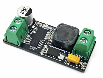
Buck Converter 12V-76V Input, 5V DC Output
40
Views
0
Tested
Compact DC-DC Converter with Input 24V and
[email protected]
Output
184
Views
0
Tested
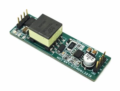
Isolated Power Supply with 24V Input and Dual 15V Output
141
Views
0
Tested
Simple Photovoltaic Charger – Solar Power module with Ba...
133
Views
0
Tested
3.3V Automotive Step-Down Regulator – Low-Iq, Dual-Mode
114
Views
0
Tested
Multi Output Step-Down Converter – Input 18-24V and Outp...
191
Views
0
Tested
Isolated Flyback Converter with 18V-28V Input and 12V Output
189
Views
0
Tested
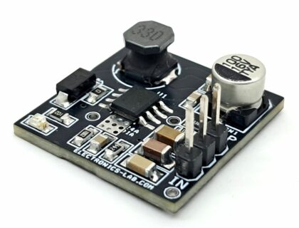
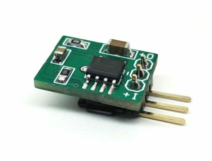
Boost Converter – Input 3.3V, Output 5V@500mA
117
Views
0
Tested
Pages:
1
2
3
4
5
6
7
...
16
»
TOP PCB Companies