

audioguru
-
Posts
12,026 -
Joined
-
Last visited
-
Days Won
13
Content Type
Profiles
Forums
Events
Everything posted by audioguru
-

LED Flasher Chaser Circuit with or Without IC
audioguru replied to Aman bharti's topic in Electronic Projects Design/Ideas
Using a single color red LED: A CD4017 powered from 9V can output 16mA into a 2V red LED on each output which is enough to burn out its output transistors. Use 150 ohm series current-limiting resistors to share the heat. -
The frequency of FM broadcasting is high enough so that the signals go straight and far if there is nothing blocking them. But the curvature of the earth blocks distant reception. Of course the range depends on the transmitting power and direction, and the sensitivity and direction of the receiver. My FM transmitter circuit produces about 0.28W into a 75 ohms 80cm whip antenna. Its range is 2km across a large river valley to a very sensitive home stereo tuner or car radio, down the street to a cheap Sony Walkman radio, and across the street to a cheap clock radio. The tx and rx antennas must be parallel to get these ranges. There is an FM radio station about 50km away from me with its antenna mounted on a small mountain. They get complaints of poor reception due to hills that block their signal.
-
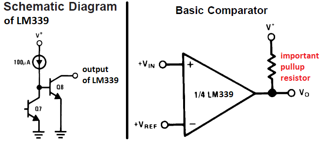
How can you use an LM339 without reading its datasheet? Since its output is "open collector" then it cannot turn on the transistor unless you add a "pullup resistor". The output of your 10A rectifier does not connect to "regulator in". Instead it has a huge filter capacitor (12000uF) and it powers the driver and output transistors of the regulator circuit. R13 should connect to the fixed +40V. When you switch taps then the huge filter capacitor must instantly charge with an enormous current that will burn out or weld the relay contacts.
-
Each comparator in an LM339 has an output current of only 4mA. Relay coils need more current so transistors or Fets must be in between. Your block diagram is missing the huge filter capacitor needed that might burn out the relay contacts when the relays switch taps.
-
You should always read the datasheet for an electronic part to see what is needed and why. The datasheet for an LM317 shows an input to ground disc capacitor of 0.1uF and an output to ground electrolytic capacitor of 25uF or more. The datasheet shows the more expensive LM117 that can use a resistor as high as 240 ohms from ADJ to OUT pins, a cheaper LM317 needs 120 ohms max. Then your 360 resistor should be 180 ohms. Solderless breadboards cause many connection problems. Solder all the connections together on a pcb or stripboard to eliminate the connection problems.
-
Simply test voltages in the circuit with a voltmeter. The opamp U2 controls output voltage regulation and it has an extremely high internal voltage gain (220 thousand times for a TLE2141). The negative feedback of the circuit detects any output voltage loss and directs U2 to correct it. I think your poor voltage regulation is caused by the wiring from the output of the circuit to your load is too thin and causes the voltage loss.
-
You forgot to attach your schematic so we can see the resistor values and important input and output capacitor values. Maybe the wallwart has very poor or no filtering then its "12V" is fluttering, averaging a voltage much less than the minimum of 5V that the LM317 needs. Maybe the wallwart is overloaded since you did not say how many LEDs or how much current they need. The original AA cells are pretty big and can produce a lot of current.
-
battery level indicator
audioguru replied to Aman bharti's topic in Electronic Projects Design/Ideas
The LM3914 in a DIP case is not made anymore. Buy them before they are all gone. -
The original defective circuit had many overloaded parts that will blow up. The improved version fixes it. Opamp U3 senses the output current in R7 and reduces the output voltage and output current to match the current set with P2. The maximum output current is 3.0A in the improved circuit and the two output transistors have a total maximum current rating of 30A so they will not blow up with only 3.0A.
-
No. An old condenser mic uses 48V and needs a preamp with a very high input impedance. It does nothing in your circuit. A modern electret mic (look it up in Google) is a condenser mic with 48V stored permanently in its electret material and has a Jfet inside that has a very high input impedance. The datasheets of electret mics show that the Jfet current is about 0.5mA and needs 2V to 10V, so your circuit will not work since the current in the 47K resistor reduces the voltage and current much too low. For 2.5V across a 0.5mA electret mic and a 5V supply then the resistor must be only (5V - 2.5V)/0.5mA= 5k but the 5k resistor and any other load (your volume control) loads down the output level. I use a 10k resistor and an 8V supply. Then it feeds a preamp with a 100K input impedance.
-
The datasheet of a CD4017B shows that its output current into a 2V LED when it has a 5V supply is only 3.5mA or less (looks dim). Your circuit is mixing an old TTL 555 with an output voltage fairly low with a Cmos 4017 that needs a fairly high clock input voltage. A bad mix. I used a 74HC4017 (high current Cmos) clocked with a Cmos 555 and it makes very bright LEDs and since they are both Cmos they work together reliably.
-
Why do you show an LT1038? it is obsolete and is not made anymore. It is impossible for it to dissipate 32V x 10A= 320W. Its datasheet shows that with a huge heatsink with fan or with liquid nitrogen for cooling it can dissipate only 120W. Its control circuit gives 10A only when its input to output is a few volts and cuts the max current to 2.5A when the input to output is 30V.
-
Transistor basic connection for switching
audioguru replied to Aman bharti's topic in Electronic Projects Design/Ideas
Why do you show text that talks about an NPN transistor but you show a schematic with a PNP transistor? The Circuitspedia PNP circuit is missing the important diode parallel with the relay coil. The diode is shown on their NPN circuit. -
Surface mount ICs on adapters? Solder that was dripped on from up high and heated with a blow torch? All I can say after seeing your project is "EEK!".
-
No and No. U1 has a gain of 2 times and a 5.6V Zener diode. Therefore its output is 11.2V, not 33V. A 5.6V Zener diode does not change its voltage when its temperature changes but an 11.2V Zener diode increases its voltage if it gets warmer. The BD139 and the output transistors are emitter-followers. Their emitter voltage follows their base voltage but at high current, their base voltage is 1V to 1.5V higher than their emitter voltage. Then when the output voltage is 30V the output of U2 must be 32V to 32.5V.
-
My Rev 6 July, 2014 schematic shows that opamp U1 makes the 11.2V reference, U2 is for the voltage control and drives the output driver transistor with 0V to about +32V and U3 is for the current control and has an output from -1.0V to about +27V. If the output has a low voltage (or is shorted) and a high current then the NPN output transistor in U2 will get hot. A tiny little surface mount package cannot dissipate much heat.
-
I did not calculate it but I think a tiny surface mounted opamp for position U2 will get too hot if the hFE of the driver and/or output transistors is low.
-
Changing just the AC Frequency
audioguru replied to Tingobap's topic in Electronic Projects Design/Ideas
If you make a circuit that uses high frequency pulse-width-modulation for making the 60Hz sinewave then its could be 90% efficient and produce "only" 120W of heat when its output is 1200W. Then it would need a pretty big heatsink with cooling fins. -
Changing just the AC Frequency
audioguru replied to Tingobap's topic in Electronic Projects Design/Ideas
Use the 120VAC 50Hz to drive a 110V 60Hz motor driving an alternator. Use magic to adjust the frequency Make an audio amplifier powered from 120VAC 50Hz with 120VAC 10A (1200W!) output and feed it a 60Hz sinewave. -
Maybe you use the power supply to test a 3A forward biased diode. Then the output transistor gets very hot.
-
Good luck trying to cool 114W so that the case is not too hot.
-
I wrongly typed 114A instead of 114W. A single 2N3055 will be at its maximum allowed chip temperature of 200 degrees C when it dissipates 115W and its case is cooled to no more than 25 degrees C with liquid nitrogen or something. A heatsink also gets hot even when it is huge and has a fan blowing on it. I never operate a transistor anywhere near its maximum temperature, voltage or current. Then it is reliable.
-
Your idea to use only one 2N3055 output transistor will have it burning hot (38V x 3A= 114A!) if the current is set to 3A and the output is shorted or has a very low voltage. Two output transistors share the heat. Their emitter resistors match them pretty well. Two output transistors at b1.5A each will have a higher hFE than only one transistor at 3A then the driver transistor does not need to supply a higher current and it also stays cooler.
-
The peak of 30.5VAC is 30.5V x 1.414= 43.13V. The bridge rectifier has diode voltage drops of 1.4V when there is no load so the positive supply will be 43.13V - 1.4V= 41.73V. If your mains electricity voltage rises then the opamps might be destroyed. I do not know why your voltage measurements are wrong. A 28VAC transformer is about 29VAC with no load. Then its peak is 41.0V and the bridge rectifier reduces it to 39.6V with no load which is fine for the 44V opamps.
-
15A output current is much too high for this circuit designed for a maximum of 3A using two output transistors to share the heat. Your schematic shows only one 2N3055 output transistor so its maximum output current will be only 1.5A. There are three MC34071 ICs. Which one do you have a problem? You said, "I did not get the circuit". It is not English, what do you mean to say??

